
Passive optical distribution
Match splitter or WDM architecture to wavelength plan, ratio, package and insertion-loss targets.
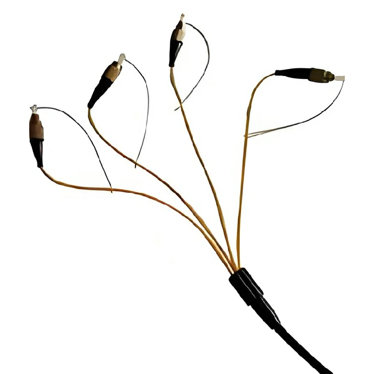
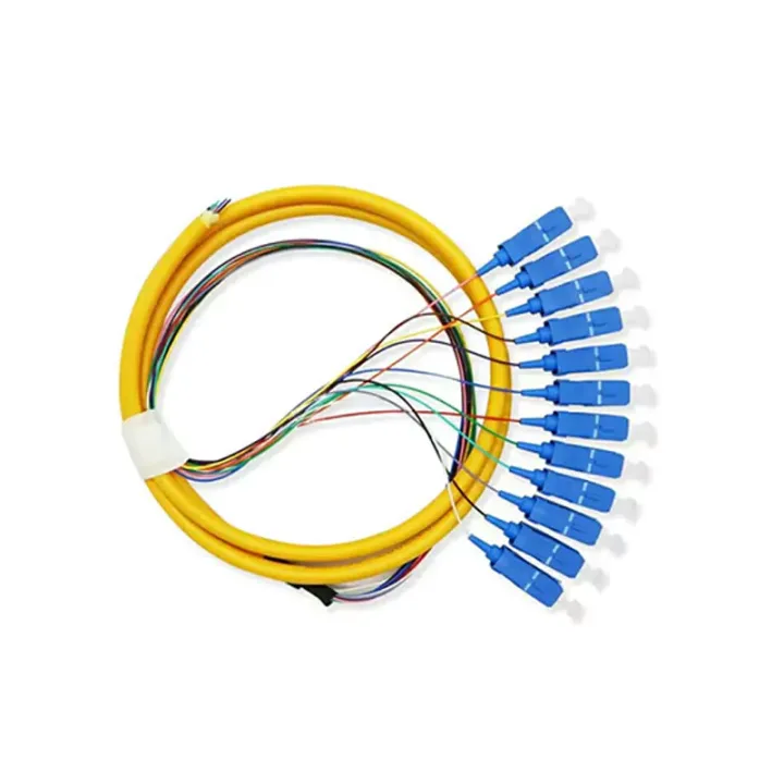
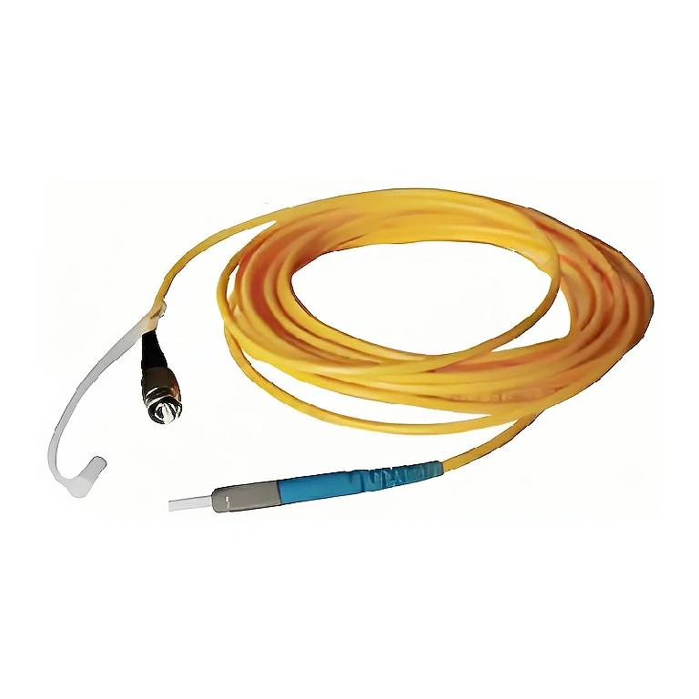
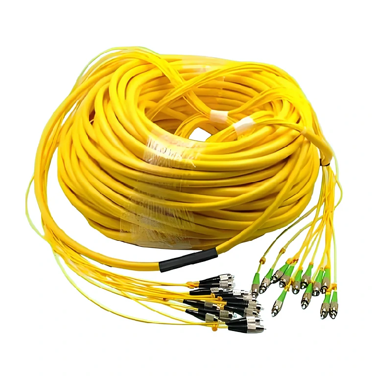
A branched multi-core pigtail assembly using standard connector plugs, with 2, 4, 6 and 8-fiber options and optional armored cable.
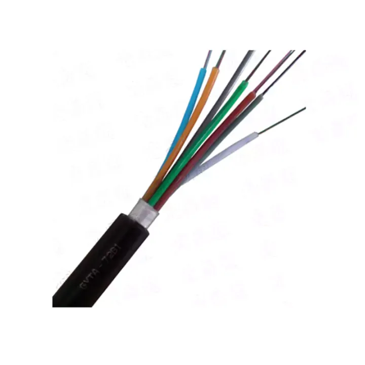
Fn Series Multifiber Fan-Out Pigtail Assemblies combine a multi-core cable, branching components and standard connector plugs into a managed fan-out assembly. Listed core-count options include 2, 4, 6 and 8 fibers, allowing several optical paths to enter a cabinet or equipment area through one coordinated cable assembly.
The assembly can use an armored cable option and 2 or 3 mm branch legs. End-face polish and optical performance differ between single-mode PC, UPC or APC and multimode PC configurations, so the branch schedule must identify every endpoint.
Define fiber mode, total core count, connector and polish per branch, branch numbering, main-cable construction, fan-out length and overall length. The current optical table lists -40°C to 80°C, but final suitability depends on the selected cable and connectors.
Huijue Group can manufacture drawing-based fan-out pigtails and review OEM or private-label identification. A branch map or physical sample helps prevent channel errors; armor, dimensions, connector mix, test results, quantity and tooling require confirmation.
| Parameter | Single-Mode (SM) | Multi-Mode (MM) | ||
| PC | UPC | APC | PC | |
| Return Loss (dB) | ≥45 | ≥50 | ≥60 | ≥35 |
| Insertion Loss (dB) | ≤0.2 (Typical Value), ≤0.3 (Maximum Value) | |||
| Repeatability (dB) | ≤0.1 | |||
| Plugging/Unplugging Cycles (Times) | ≥500 | |||
| Operating Temperature (℃) | -40~+80 | |||
Support the branching point, maintain bend radius on every leg and prevent branch labels from sliding or becoming ambiguous. Armored construction should be grounded or bonded only as required by the approved cable design and site practice.
Buyer Questions
Answers specific to Fn Series Multifiber Fan-Out Pigtail Assemblies selection, configuration and purchasing.
A mixed branch schedule can be reviewed. Each channel, connector and polish must be shown clearly on the approved drawing.
It may be considered where the main cable needs added mechanical protection, subject to pathway, bend and termination constraints.
Use the deployment context to narrow the configuration before comparing dimensions, capacities and options.
Match splitter or WDM architecture to wavelength plan, ratio, package and insertion-loss targets.
Coordinate connector, polish, fiber grade, polarity and cable length across patching points.
Plan MPO/MTP trunks and harnesses around port mapping, breakout format and rack density.
Select splicing, cleaning and test tools for the connector types and measurements used on site.
Before quotation: confirm capacity, interfaces, installation environment, power conditions, quantity and required options.