
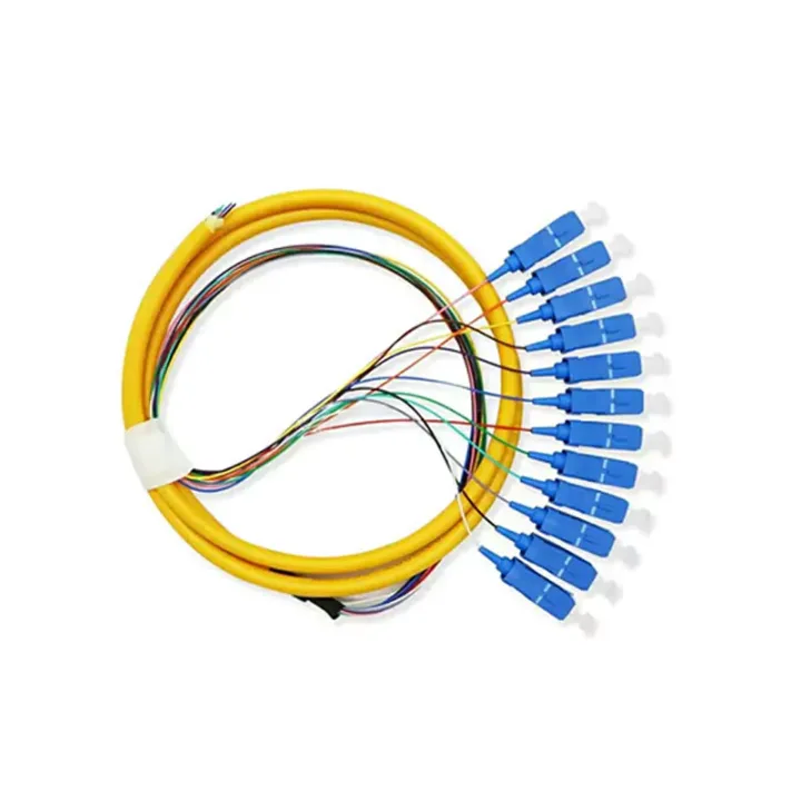
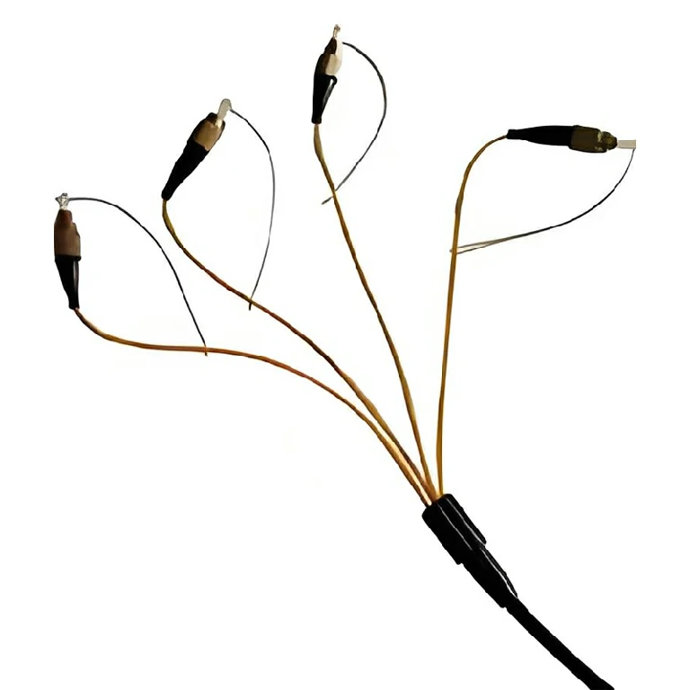
Passive optical distribution
Match splitter or WDM architecture to wavelength plan, ratio, package and insertion-loss targets.
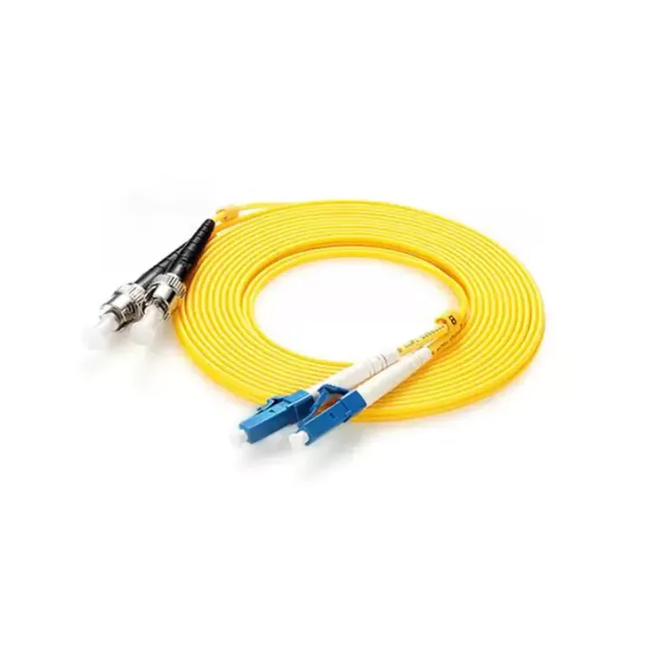
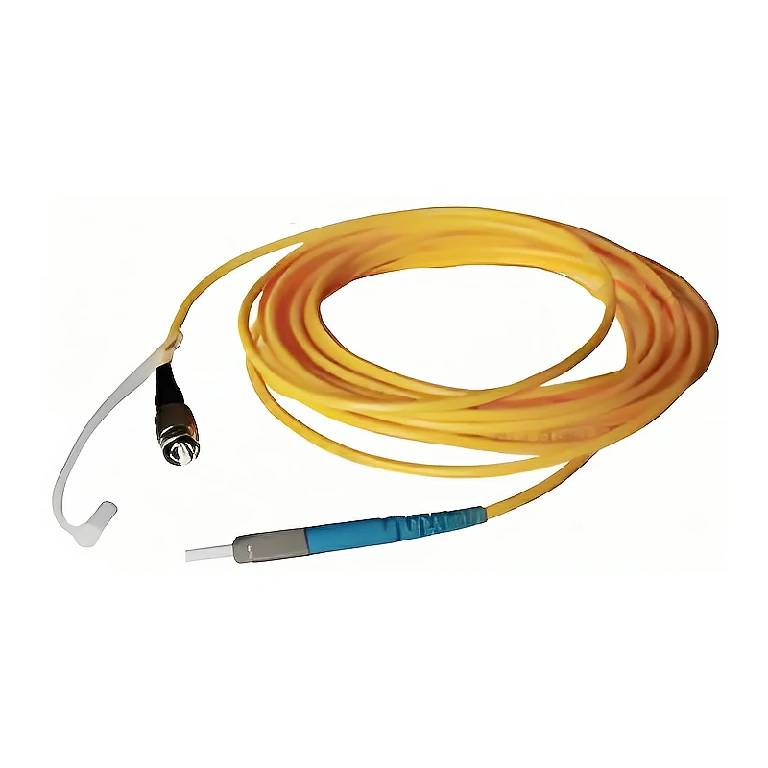
A duplex indoor fiber assembly that joins two simplex cords in a figure-eight profile for paired equipment and patching connections.
Indoor Dual-Core Fiber Optic Connector assemblies place two simplex fiber cords side by side in a figure-eight profile. The paired construction keeps transmit and receive fibers together while allowing each leg to terminate at the required optical port.
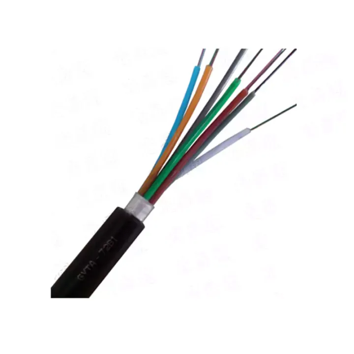
PVC and LSZH tight-buffer constructions are listed, with single-mode connector performance defined for PC, UPC and APC end faces. The source also includes multi-core mechanical data, so the final quotation should clearly distinguish a duplex cord from any higher-core cable requested.
Confirm that a true two-fiber duplex assembly is required, then specify fiber grade, connector and polish on each leg, polarity, cable diameter, overall length and any zip-cord separation length. Equipment Tx/Rx mapping should be shown on the drawing.
Huijue Group can manufacture OEM duplex assemblies from an end-to-end map or mating sample, with private-label tags and packaging. Cable color, connector mix, leg separation and test data are reviewed together; materials, tolerances and quantity remain subject to engineering confirmation.
| Number of Cores | Optical Cable Specification (mm) | Crushing Force (N/100mm) | Tensile Force (N) | Minimum Bending Radius (mm) | Weight (kg/km) | Operating Temperature (℃) | |||
| Short-Term | Long-Term | Short-Term | Long-Term | Dynamic | Static | ||||
| 4 | 6.5 | 10000 | 3000 | 800 | 500 | 65 | 130 | 50 | -40~85 |
| 6 | 6.5 | 10000 | 3000 | 800 | 500 | 65 | 130 | 50 | -40~85 |
| 8 | 7.5 | 10000 | 3000 | 1000 | 500 | 75 | 130 | 60 | -40~85 |
| 12 | 7.5 | 10000 | 3000 | 1000 | 500 | 75 | 130 | 60 | -40~85 |
Optical Performance Indicators of Single-Mode Fiber Connectors Unit: dB
| Serial No. | Item Name | Single-Mode (1310nm and 1550nm) | ||||||
| Insertion Loss | Additional Loss | Return Loss | Return Loss Variation | |||||
| PC, UPC Type | APC Type | PC Type | UPC Type | APC Type | ||||
| A | Before Test | ≤ 0.35 | ≤ 0.35 | ≥ 45 | ≥ 50 | ≥ 60 | ||
| B | Interchangeability Test | ≤ 0.5 | ≤ 0.5 | ≥ 43 | ≥ 48 | ≥ 58 | ||
| C | Mechanical Durability | ≤ 0.5 | ≤ 0.5 | ≤ 0.2 | ≥ 43 | ≥ 48 | ≥ 58 | ≤ 5 |
| D | Tensile Test | ≤ 0.5 | ≤ 0.5 | ≤ 0.2 | ≥ 43 | ≥ 48 | ≥ 58 | ≤ 5 |
| E | High Temperature Test | ≤ 0.5 | ≤ 0.5 | ≤ 0.2 | ≥ 43 | ≥ 48 | ≥ 58 | ≤ 5 |
| F | Low Temperature Test | ≤ 0.5 | ≤ 0.5 | ≤ 0.2 | ≥ 43 | ≥ 48 | ≥ 58 | ≤ 5 |
| G | Damp Heat Test | ≤ 0.5 | ≤ 0.5 | ≤ 0.2 | ≥ 43 | ≥ 48 | ≥ 58 | ≤ 5 |
| H | Salt Spray Test | ≤ 0.5 | ≤ 0.5 | ≤ 0.2 | ≥ 43 | ≥ 48 | ≥ 58 | ≤ 5 |
| I | Transportation Test | ≤ 0.5 | ≤ 0.5 | ≤ 0.2 | ≥ 43 | ≥ 48 | ≥ 58 | ≤ 5 |
| * Note 1: Additional Loss = Insertion Loss after Routine Test - Insertion Loss before Test. If negative, it is zero. * Note 2: Return Loss Variation = Return Loss before Test - Return Loss after Routine Test. If negative, it is zero. | ||||||||
2) Optical Performance Indicator Requirements for Multi-Mode Fiber Connectors
a) The insertion loss (including repeatability) of any plug connected to a standard plug via a standard adapter shall be ≤ 0.2dB.
b) The insertion loss of two plugs connected via a standard adapter shall be ≤ 0.3dB.
c) After various tests, the allowable variation of insertion loss shall be ≤ 0.2dB, and the variation of return loss shall be < 5dB.
Use in an indoor protected pathway appropriate to the selected jacket. Maintain paired-fiber polarity, avoid twisting the two legs and provide strain relief where the cable separates near the connectors.
Buyer Questions
Answers specific to Indoor Dual-Core Fiber Optic Connector selection, configuration and purchasing.
No. Its primary role is a paired two-fiber, figure-eight assembly. Higher-core constructions should be quoted as a separate approved cable design.
Yes, a hybrid duplex assembly can be reviewed when both legs and the Tx/Rx polarity are shown clearly.
Use the deployment context to narrow the configuration before comparing dimensions, capacities and options.
Match splitter or WDM architecture to wavelength plan, ratio, package and insertion-loss targets.
Coordinate connector, polish, fiber grade, polarity and cable length across patching points.
Plan MPO/MTP trunks and harnesses around port mapping, breakout format and rack density.
Select splicing, cleaning and test tools for the connector types and measurements used on site.
Before quotation: confirm capacity, interfaces, installation environment, power conditions, quantity and required options.