
Equipment rooms
Organize racks, pathways and service access around active network equipment.
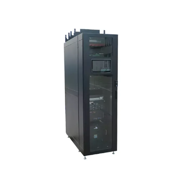
An integrated BBU cabinet combining centralized equipment space, directed cooling, site power and monitoring for access-room and convergence-room installation projects.
The Integrated BBU Cabinet with Cooling groups baseband equipment and its supporting infrastructure into a prefabricated cabinet arrangement. It addresses access and convergence rooms where multiple BBUs need coordinated power, airflow and maintenance access within a limited floor area.
Its enclosure and cooling are designed as a combined system. The source describes internal circulation, hot/cold separation and emergency ventilation; the final configuration must be matched to the BBU population and the room’s heat-rejection provisions.
Start with the BBU equipment count, dimensions, airflow direction and measured or specified heat load. The source lists a 6 kW maximum load per cabinet and a separate 10 kW IT-load support figure for the combined configuration; confirm the configuration boundary rather than adding these figures together. Review rectifier loading, battery autonomy, cooling duty and emergency ventilation as one schedule.
Huijue Group can evaluate OEM labeling and a BBU cabinet layout developed from project drawings or equipment samples. Ducts, power sections and controls require engineering agreement on feasibility, tooling, tests, quantity and delivery scope.
Send BBU models, cabinet quantity, rack elevation, DC loads, AC input, battery runtime target, cooling design conditions, alarms and required smoke, water, door or video sensors.
| J-net IM-RACK01 Configuration Form | |||
|---|---|---|---|
| Cabinet system | Cooling System | ||
| Dimensions (H x W x D MM) | 2000(2200)X 600X 1000(1200) | Rated AC Transmission Input power | 220V AC 50Hz |
| System Layout / Configuration | Cabinet-level micro-modules | Cooling capacity (L35/L35) | 3.5KW |
| Number of machines that can be merged | 2-3 units | Rated input power Rate | 1270W |
| Capacity | 42U(46U) | Rated current | 8A |
| Protection Rating | IP30 | Heating Capacity | 1000W |
| Operating Temperature | -20℃~45℃ | Refrigerant | R410A |
| Installation | Concrete floor, raised floor | Sensible Heat Ratio (SHR) | ≥0.99 |
| Maximum load per cabinet | 6KW | Energy Efficiency Ratio | ≥3.2 |
| Supports maximum power consumption of IT load | 10KW | Air distribution | Front air supply, rear air return |
| IT cabinet bearing requirements | Static load 1500kg, dynamic load 1000kg | Installation | Rack mounting |
| • Distribution System | Monitoring system | ||
| Lightning protection level | Class C, In 20ka, Imax40ka | Monitoring system | Support remote web interface access |
| Power Input | Single and dual channels optional | Local Interface | Standard 10-inch touch screen |
| Dual Power Switching System | Optional for 2-way input | Mobile O&M | Mobile App, SMS Alerts |
| Power System Capacity | 300A | Smoke detector | Optional |
| Rectifier module | 50A*6 | Water Leak Detection | Optional |
| Input Voltage | 380V 3-phase | Temperature and humidity | Optional |
| Output voltage | -48V DC | Door Lock | Optional |
| Output power factor | 0.9 | Video monitoring | Optional |
| Backup time | 15~30min | Fire Suppression System | |
| Lithium battery | Standard | Rack-Mount Fire Suppression Unit | Integrated Temperature Detection and Fire Suppression Unit |
Intended for centralized BBU installations in access rooms, convergence rooms and other indoor telecom equipment locations.
IP30 and -20°C to 45°C operation are listed. Concrete-floor and raised-floor installation are described; verify floor support, room airflow and cooling service connections.
Buyer Questions
Answers specific to Integrated BBU Cabinet with Cooling selection, configuration and purchasing.
The design uses directed airflow and coordinated cooling. Site energy use depends on equipment load, ambient conditions and controls; no project saving percentage should be assumed.
A 2–3 cabinet arrangement is documented. Confirm the equipment distribution, shared infrastructure and expansion boundary in the final design.
Several sensors and access functions are identified as optional. Request an itemized monitoring and alarm schedule for the proposed cabinet package.
The source has a 15–30 minute reference. Required autonomy must be calculated from the actual DC load, battery configuration and operating conditions.
Use the deployment context to narrow the configuration before comparing dimensions, capacities and options.
Organize racks, pathways and service access around active network equipment.
Coordinate cabinet capacity, cable routes, airflow and planned expansion.
Package network equipment within compact distributed infrastructure sites.
Add capacity while accounting for existing racks, routes and maintenance space.
Before quotation: confirm capacity, interfaces, installation environment, power conditions, quantity and required options.