
Central offices and equipment rooms
Organize high-capacity termination, cross-connection and patching with defined service access.
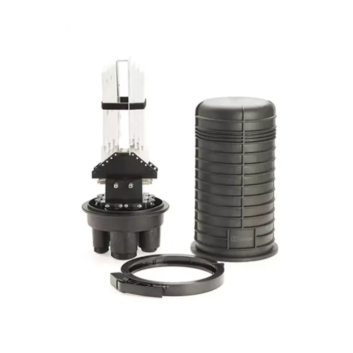
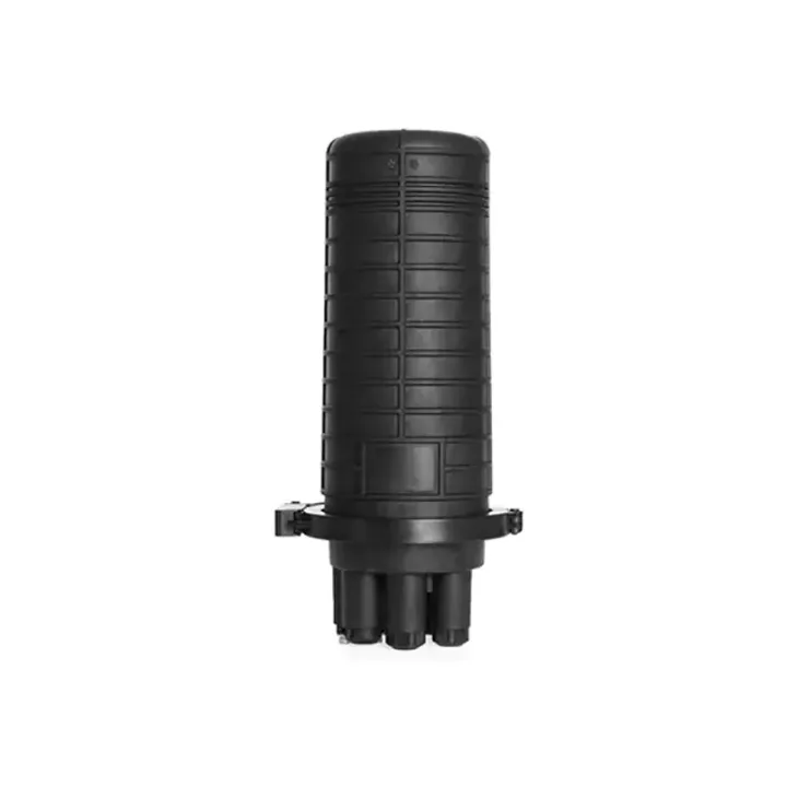
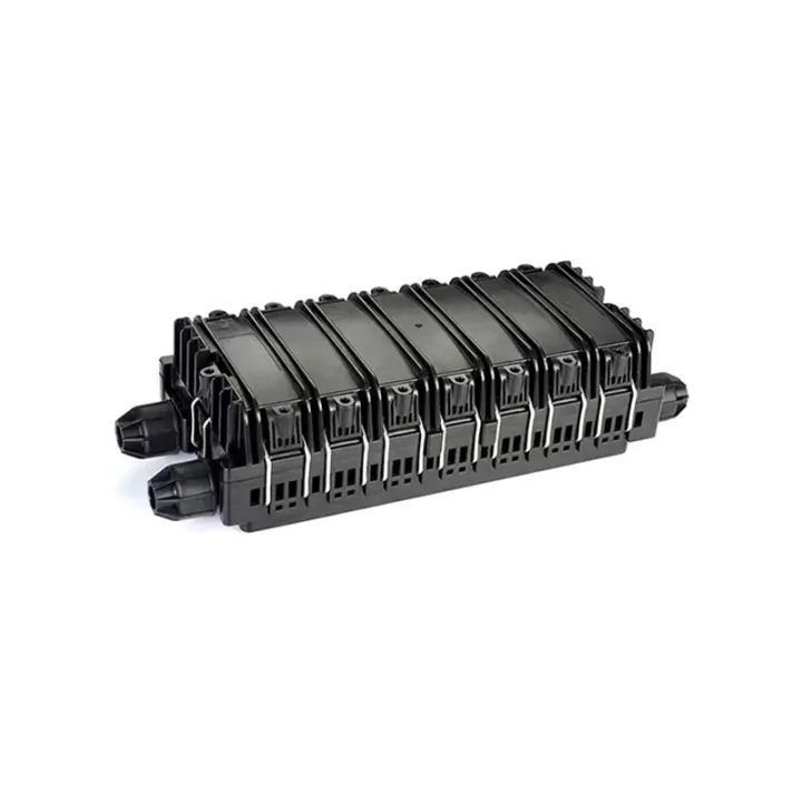
Fiber Optic Splice Closure protects optical cable joints, splice storage and route branching in a Polymer-modified plastic enclosure for maintainable fiber-network deployment.
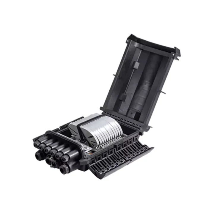
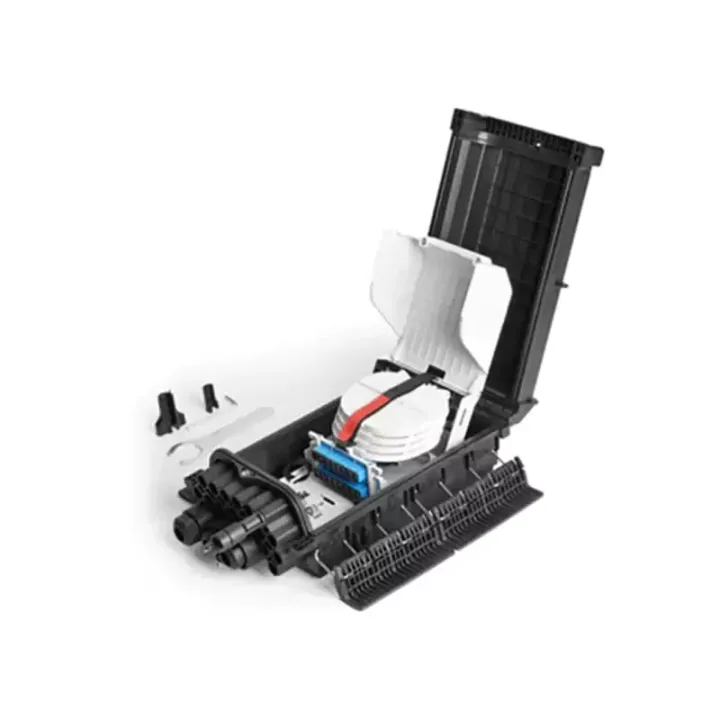
Polymer-modified plastic, an enclosure clamp, covered tray and pole kit are listed. The source refers to 10–17.5 mm cable sealing, screw compression for cut ports and direct compression for uncut ports.
The Fiber Optic Splice Closure provides a re-enterable cable connection for a reviewed wall, pole or manhole installation. Cut and uncut cable paths have different sealing requirements, so the cable route should be established before selecting the seal kit.
Overall dimensions and total tray capacity are not resolved in this source record.
Sealing descriptions include both mechanical and heat-shrink references. Obtain the exact port-section drawing and installation procedure rather than assuming a fully heat-free assembly.
Huijue Group can examine OEM joint-box configurations, private-label marks and sample/drawing-based port details. Seal feasibility, tooling, re-entry tests, quantities and delivery scope must be confirmed.
Send cable diameters, loop-through needs, splice count, mounting method and allowed sealing tools.
| Box Material | Polymer Modified Plastic | Overall Dimensions (mm) | |||||||
| Sealing Material | Polyolefin | Weight (kg) | |||||||
| Standard Accessories | |||||||||
| Serial No. | Name | Unit | Quantity | Serial No. | Name | Unit | Quantity | ||
| 1 | Box Shell (Including Hoop) | Set | 1 | 7 | Plug | Piece | 2 | ||
| 2 | Sealing Element | Set | 1 | 8 | Insulating Tape | Roll | 1 | ||
| 3 | Fiber Tray (Including Cover Plate) | Sheet | 1 | 9 | Nylon Cable Tie | Piece | 4 | ||
| 4 | Bracket Assembly | Set | 1 | 10 | Wet Wipe | Pack | 1 | ||
| 5 | Pole-mounted Mounting Kit | Set | 1 | 11 | Special Wrench | Piece | 1 | ||
| 6 | Fusion Splicing Protection Tube | Piece/Tray | 26 | ||||||
| Optional Accessories | |||||||||
| Serial No. | Name | Unit | Quantity | Serial No. | Name | Unit | Quantity | ||
| 1 | Air Nozzle | Set | 1 | 4 | Wall-mounted Mounting Kit | Set | 1 | ||
| 2 | Grounding Assembly | Set | 1 | 5 | Fiber Protection Hose | Meter | As Required | ||
| 3 | SC Adapter | Piece | As Required | 6 | Box-type Passive Optical Splitter | Piece | 1 | ||
Wall, pole and chamber fiber joints with an agreed cut/uncut cable arrangement.
IP68 is source-listed. Confirm applicable immersion conditions, cable seals and field resealing requirements.
Buyer Questions
Answers specific to Fiber Optic Splice Closure selection, configuration and purchasing.
The source descriptions conflict. Confirm the exact supplied seal system and field procedure before ordering.
One cassette passive splitter is listed as an option. Confirm packaging, support and resulting tray space.
The table leaves them blank. Obtain an approved envelope and mounting drawing for site planning.
Use the deployment context to narrow the configuration before comparing dimensions, capacities and options.
Organize high-capacity termination, cross-connection and patching with defined service access.
Place splitter, terminal and distribution boxes at the correct feeder-to-drop transition.
Protect branching and splicing around cable entries, sealing, tray capacity and mounting method.
Reserve fibers, ports and internal routing space for staged subscriber or backbone growth.
Before quotation: confirm capacity, interfaces, installation environment, power conditions, quantity and required options.