
Direct answer
Factory termination offers controlled assembly and test conditions when lengths and end configurations are stable. Field assembly supports variable routes and repairs but depends on compatible tools, fibre preparation, cleanliness and acceptance testing; compare installed cost and rework risk, not connector price alone.
Within the broader Passive Optics & Connectivity workflow, this article focuses on field assembled fiber connector: choose a termination method from route uncertainty, volume and quality-control capability. Confirm route-length variation and the evidence for the offered product before final engineering approval.
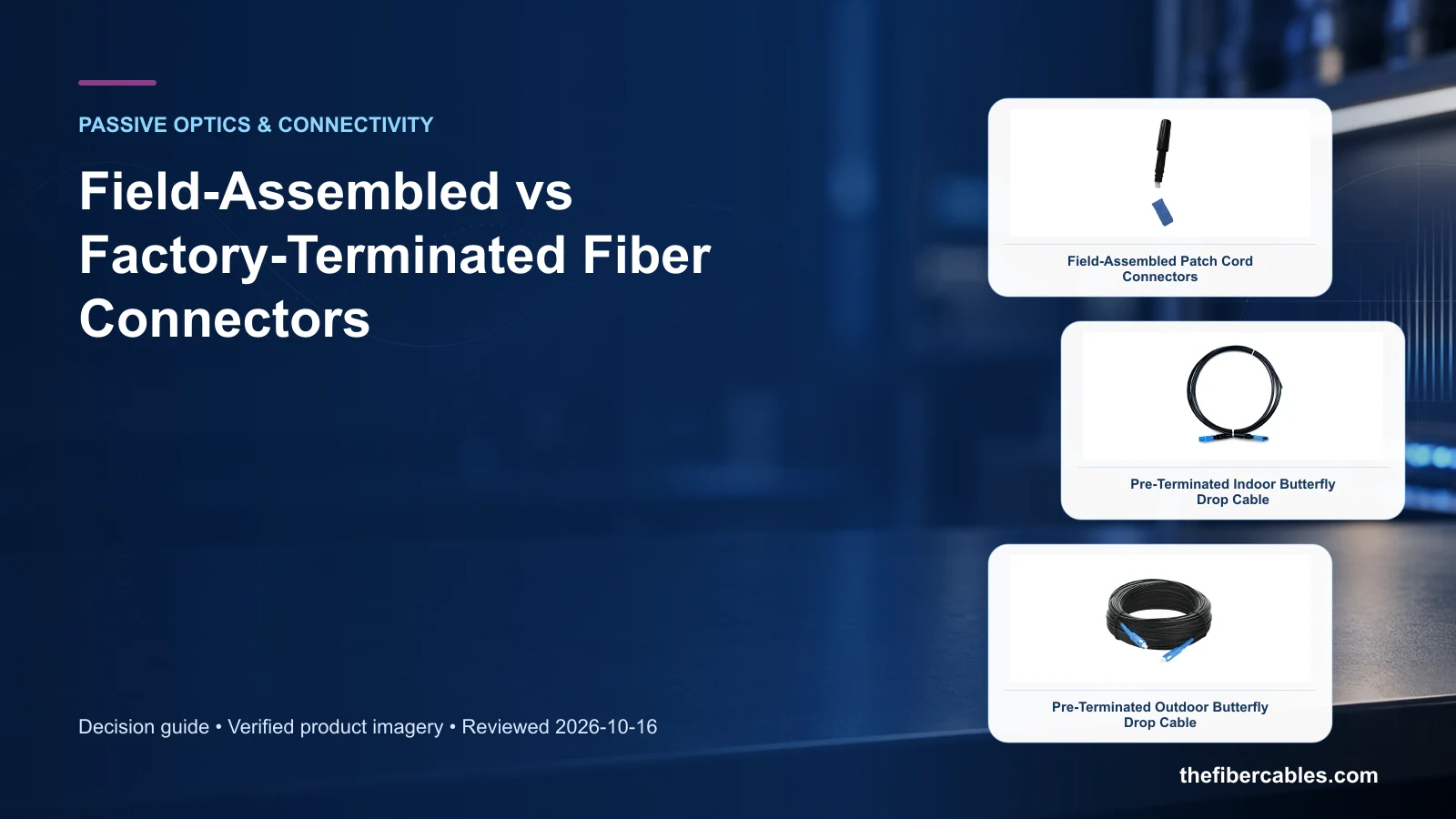
Decisions that separate the options
Choose a termination method from route uncertainty, volume and quality-control capability. Start with the operating requirement and installation boundary, then separate system requirements from product claims so each supplier knows which evidence must accompany the offered configuration.
- Quantify route-length variation and installation volume.
- Confirm installer tools and training for the connector system.
- Specify inspection and optical acceptance at the work face.
Quantify route-length variation and installation volume
Capture Route-length variation, then use Factory terminated as a practical comparison point: Repeatable length and connector map. Before approval, verify this point: Length tolerance and factory test record.
Confirm installer tools and training for the connector system
Capture Connector and fibre type, then use Field assembled as a practical comparison point: Variable path or restoration work. Before approval, verify this point: Tool compatibility and installer process.
Specify inspection and optical acceptance at the work face
Capture Installation quantity, then use Hybrid strategy as a practical comparison point: Main runs are fixed but drops vary. Before approval, verify this point: Clear boundary and separate acceptance records.
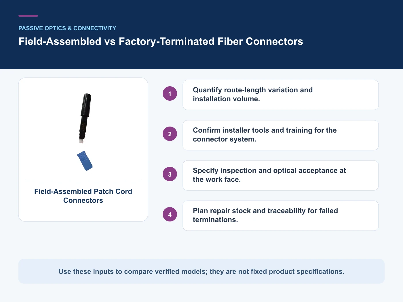
Where the options diverge
This table connects splitter technology and packaging, wavelength plans, connector interfaces, field termination and splice protection to the decision on field assembled fiber connector. It is a decision aid rather than a universal performance table: exact capacity, environmental class, electrical or optical limits and certifications must come from the selected model, applicable project documents and verifiable test evidence.
| Option or input | When it fits | What must be verified |
|---|---|---|
| Factory terminated | Repeatable length and connector map | Length tolerance and factory test record |
| Field assembled | Variable path or restoration work | Tool compatibility and installer process |
Reference point: IEC 61755-1: Connector optical interfaces for single-mode fibres and IEC 61300-3-35: Visual inspection of fibre optic connector endfaces frame the terminology or method used for this field assembled fiber connector comparison. They do not approve a product configuration; apply the edition named by the contract and local authority.
Relevant products from our communications portfolio
The products below connect the field assembled fiber connector decision to real catalogue families and verified site photography. They are starting points, not a claim that every configuration described here is a standard stock item; confirm model, interface, rating, drawing and testing scope with the project team.
- Field-Installable Fiber Optic Connectors — use this product page as a configuration reference when you quantify route-length variation and installation volume. Confirm the offered model, interfaces, drawings and available evidence before quotation.
- Pre-Terminated Indoor Butterfly Drop Cable — use this product page as a configuration reference when you confirm installer tools and training for the connector system. Confirm the offered model, interfaces, drawings and available evidence before quotation.
- Pre-Terminated Outdoor Butterfly Drop Cable — use this product page as a configuration reference when you specify inspection and optical acceptance at the work face. Confirm the offered model, interfaces, drawings and available evidence before quotation.
For adjacent configurations, browse Fiber Components & Connectivity and compare those options against the field assembled fiber connector inputs above, including route-length variation.
A comparison workflow that avoids label-based selection
- Step 1: Define the operating scenario and document route-length variation. Record Route-length variation as an explicit input. Length tolerance and factory test record.
- Step 2: Map interfaces, installation constraints and connector and fibre type. Record Connector and fibre type as an explicit input. Tool compatibility and installer process.
- Step 3: Compare candidate configurations against the decision table and record exceptions. Record Installation quantity as an explicit input. Clear boundary and separate acceptance records.
Common mistakes to avoid
- Selecting from a catalogue image before route-length variation is fixed.
- Treating a category-page description as model-specific compliance evidence.
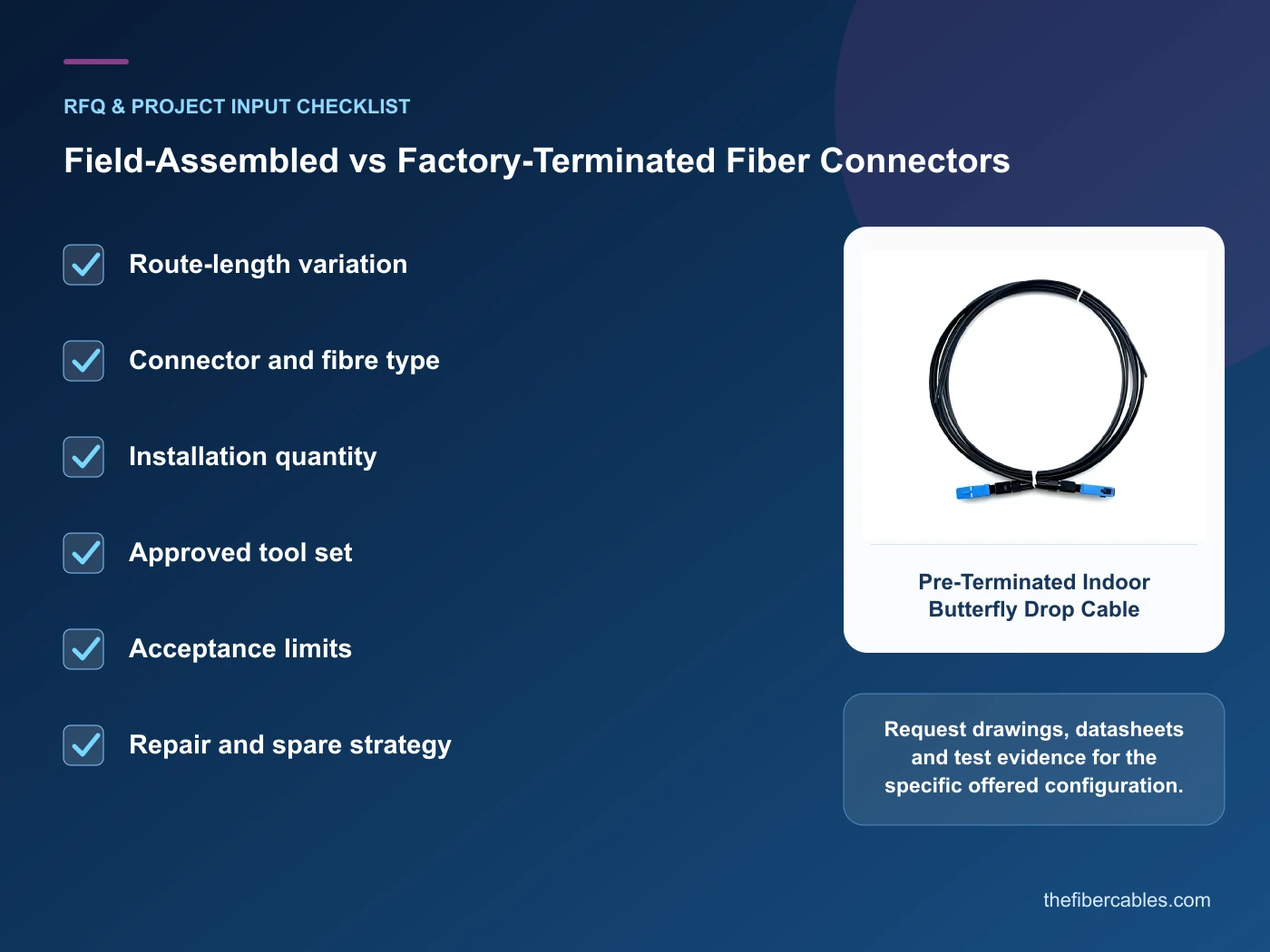
What to include in the RFQ or design input
For field assembled fiber connector, a complete request reduces back-and-forth and prevents a catalogue image from being mistaken for a verified configuration. Record the following fields, identify which values are mandatory or provisional and attach route, interface or layout drawings where relevant.
- Route-length variation
- Connector and fibre type
- Installation quantity
- Approved tool set
- Acceptance limits
- Repair and spare strategy
Questions engineers and buyers ask
How should factory terminated be evaluated for field assembled fiber connector?
Use repeatable length and connector map as the operating context, record route-length variation, and verify length tolerance and factory test record for the exact offered configuration.
Which project input can change the field assembled fiber connector decision?
Quantify route-length variation and installation volume. Recheck that decision when connector and fibre type or installation quantity changes.
Sources and standards
These sources support the method and vocabulary used in this guide. They are not a substitute for project requirements or evidence tied to the exact field assembled fiber connector configuration.
- IEC 61755-1: Connector optical interfaces for single-mode fibres (2022, Ed.2). Use it to verify the terminology and scope relevant to field assembled fiber connector; the source does not certify a specific offered product.
- IEC 61300-3-35: Visual inspection of fibre optic connector endfaces (2022, Ed.3). Use it to verify the terminology and scope relevant to field assembled fiber connector; the source does not certify a specific offered product.
- IEC 61280-4-2: Installed single-mode cabling attenuation and optical return loss (2024, Ed.3). Use it to verify the terminology and scope relevant to field assembled fiber connector; the source does not certify a specific offered product.
Source review: Links and cited editions for field assembled fiber connector were checked on 2026-10-16. Confirm the edition adopted by the project contract and the authority having jurisdiction.
Related guidance
PLC vs FBT Optical Splitters: Ratio, Wavelength and Packaging Decisions • APC vs UPC Fiber Interfaces: Where Polish, Adapter Color and Return Loss Matter • Fusion Splice Protection Sleeves: Fibre Count, Heater and Tray Compatibility
Prepare a field assembled fiber connector configuration for review
For a project review, provide route-length variation, connector and fibre type, installation quantity, approved tool set. The response can separate standard options, customization points and information still required before quotation.
——END——