
Passive optical distribution
Match splitter or WDM architecture to wavelength plan, ratio, package and insertion-loss targets.
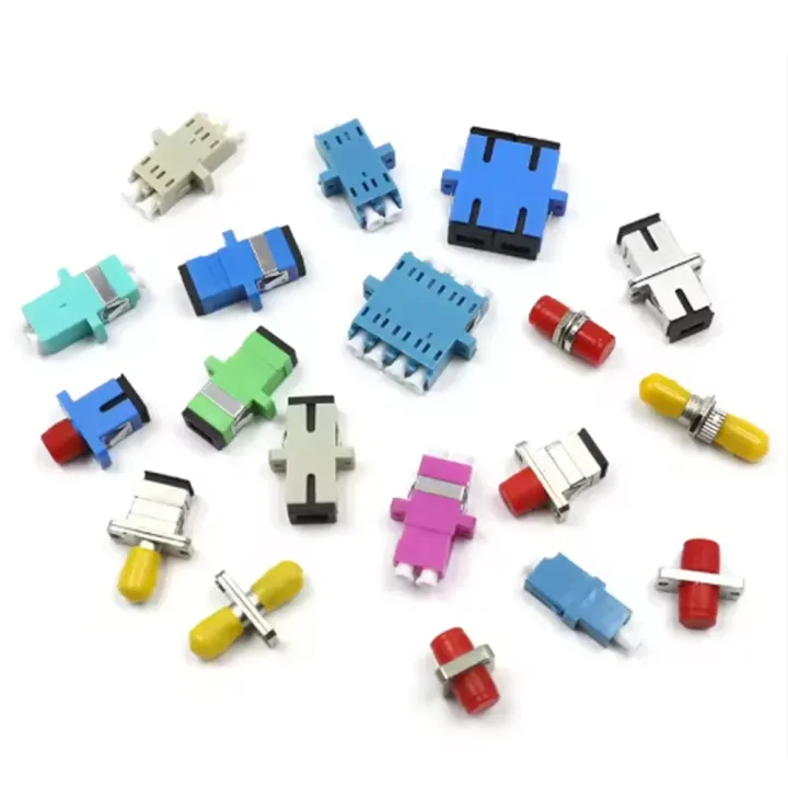
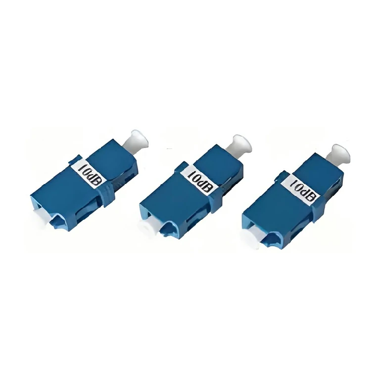
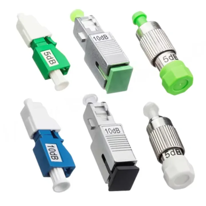
SC, LC, FC and ST fiber adapters for aligning two connector plugs, with simplex/duplex, UPC/APC and single-/multimode options.
Fiber Optic Adapters provide the alignment sleeve between two connector plugs in a panel, frame or equipment interface. The series includes FC, LC, SC and ST formats, with single-port and dual-port flange options represented in the current product record.
Adapter selection is more than choosing the housing shape. Connector family, UPC or APC geometry, single-mode or multimode sleeve, simplex or duplex density, flange and panel cutout must all match the application.
Specify connector family, polish, fiber mode, simplex/duplex, sleeve material, flange style, panel thickness and cutout. APC and UPC adapters should be kept distinct in the panel layout, and color coding should follow the approved network convention.
Huijue Group can review OEM or private-label adapter assortments, panel-specific flange variants and drawing-based packaging. A customer panel or adapter sample can support fit checks. Mold/tooling, sleeve, color, optical test, quantity and delivery scope require engineering confirmation.
| Single Port | FC Single-port Flange Adapter |
|---|---|
| Single Port | LC Single-port Flange Adapter |
| Single Port | SC Single-port Flange Adapter |
| Single Port | ST Single-port Flange Adapter |
| Dual Port | LC Dual-port Flange Adapter |
| Dual Port | SC Dual-port Flange Adapter |
Keep protective caps installed until use, clean mating connectors and prevent dust from entering the sleeve. The surrounding panel or enclosure determines mechanical and environmental protection.
Buyer Questions
Answers specific to Fiber Optic Adapter selection, configuration and purchasing.
It should not be. APC and UPC end-face geometries differ; use a matching adapter and clearly identify the panel port.
A simplex adapter mates one fiber pair; a duplex housing places two mating channels together for higher panel density.
Yes, a panel drawing or sample can be reviewed, subject to flange, clip, thickness and tooling feasibility.
Use the deployment context to narrow the configuration before comparing dimensions, capacities and options.
Match splitter or WDM architecture to wavelength plan, ratio, package and insertion-loss targets.
Coordinate connector, polish, fiber grade, polarity and cable length across patching points.
Plan MPO/MTP trunks and harnesses around port mapping, breakout format and rack density.
Select splicing, cleaning and test tools for the connector types and measurements used on site.
Before quotation: confirm capacity, interfaces, installation environment, power conditions, quantity and required options.