
Passive optical distribution
Match splitter or WDM architecture to wavelength plan, ratio, package and insertion-loss targets.
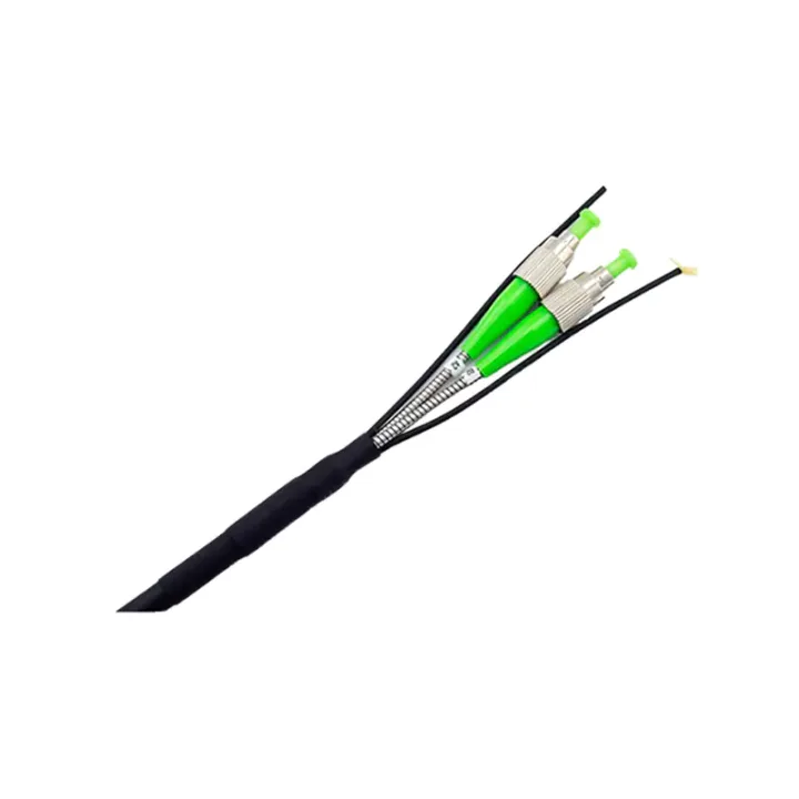
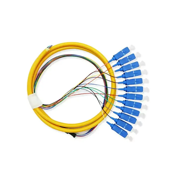
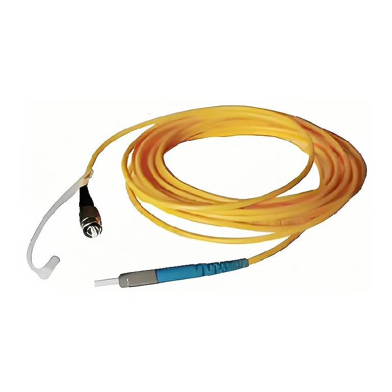
Connectorized remote fiber cable for BBU-to-RRU extension within a site, designed for vertical, horizontal, indoor and outdoor routing conditions.
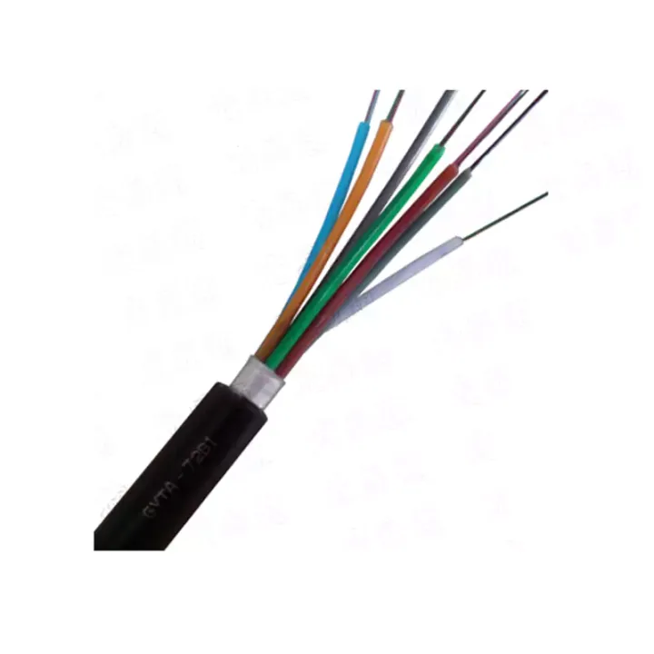
Remote radio unit (RRU) fiber optic cable assemblies provide the connectorized fiber path between baseband and remote radio equipment. The assembly can be used directly over the site route or as the equipment-end connection after a longer outdoor cable section crosses buildings, corridors or ducts.
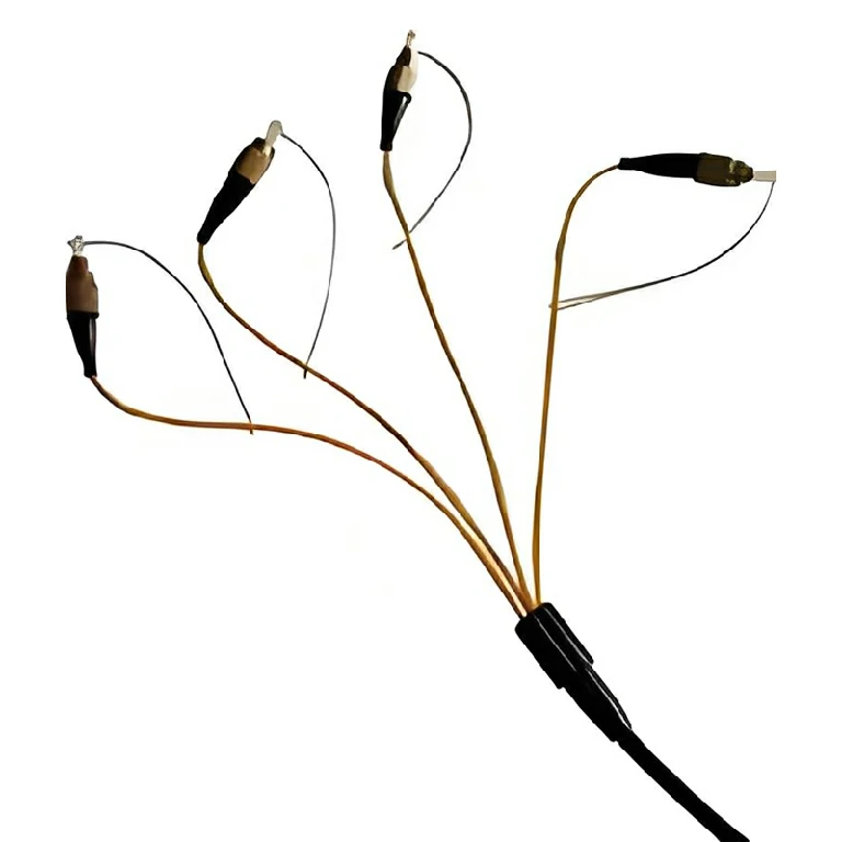
The cable is designed around flexible routing, small bend radius, abrasion resistance and construction strength. Because the assembly connects named equipment ports, the fiber type, connector and polish at both ends, breakout structure and exact length must be defined before production.
Provide the BBU and RRU optical interfaces, fiber category, core count, connector/polish combination, main and breakout diameters, length and end orientation. Route lightning exposure and grounding strategy must be reviewed at system level; a non-metallic or protected fiber path does not replace the site's surge and bonding design.
Huijue Group can manufacture drawing-based remote fiber assemblies with customer-defined end mapping, neutral or private-label packaging and project labels. Equipment samples can be reviewed when the interface is uncertain. Cable structure, connector compatibility, tests, drum or coil packaging and quantity require engineering confirmation.
| Fiber Category | B1.1 and B1.3 | B4 | B6 | ||||||
| Operating Wavelength (nm) | 1310 | 1550 | 1625 | 1550 | 1625 | 1310 | 1550 | 1625 | |
| Attenuation Coefficient (Maximum Value) (dB/km) | Class Ⅰ | 0.36 | 0.23 | 0.26 | 0.22 | 0.27 | 0.38 | 0.24 | 0.28 |
| Class Ⅱ | 0.40 | 0.26 | 0.30 | 0.25 | 0.30 | 0.50 | 0.30 | 0.40 | |
| Note: The product is only tested at the wavelengths required by the user. | |||||||||
| Fiber Type | A1a.1 | A1a.2 | A1b | |||
| Operating Wavelength (nm) | 850 | 1300 | 850 | 1300 | 850 | 1300 |
| Attenuation Coefficient Class (Maximum Value) (dB/km) | 2.4 3.0 3.5 | 0.7 1.0 1.5 | 2.5 | 0.8 | 2.8 3.5 | 0.7 1.0 1.5 |
| Modal Bandwidth Class (Minimum Value) (MHz-km) | 200 500 800 | 200 500 800 1000 1200 | 1500 2000 (Effective Modal Bandwidth) | 500 | 100 200 500 800 | 200 500 800 1000 |
| Note: Unspecified bandwidth values are overfilled launch bandwidth values. | ||||||
Note: The above coefficients do not include the insertion loss of connectors. If connectors are included, a loss of 0.35dB shall be added.
Confirm the outdoor exposure, pathway, bend radius, pulling load, entry sealing and strain relief for the full route. Protect connector ends during installation and verify the complete assembly against the equipment vendor's port and optical budget.
Buyer Questions
Answers specific to RRU Fiber Optic Cable Assemblies selection, configuration and purchasing.
Yes, the source describes direct routing as one option. A longer outdoor backbone with connectorized equipment ends is another, depending on the site.
A hybrid end configuration can be reviewed from the equipment-port schedule and approved fiber map.
No. The whole site's cable construction, equipment, grounding and surge-protection arrangement must be engineered together.
Use the deployment context to narrow the configuration before comparing dimensions, capacities and options.
Match splitter or WDM architecture to wavelength plan, ratio, package and insertion-loss targets.
Coordinate connector, polish, fiber grade, polarity and cable length across patching points.
Plan MPO/MTP trunks and harnesses around port mapping, breakout format and rack density.
Select splicing, cleaning and test tools for the connector types and measurements used on site.
Before quotation: confirm capacity, interfaces, installation environment, power conditions, quantity and required options.