
Passive optical distribution
Match splitter or WDM architecture to wavelength plan, ratio, package and insertion-loss targets.
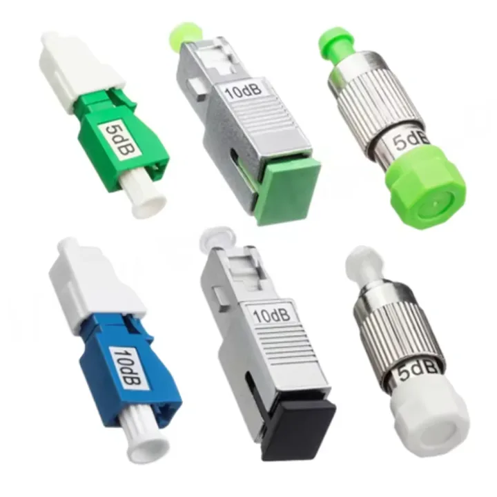
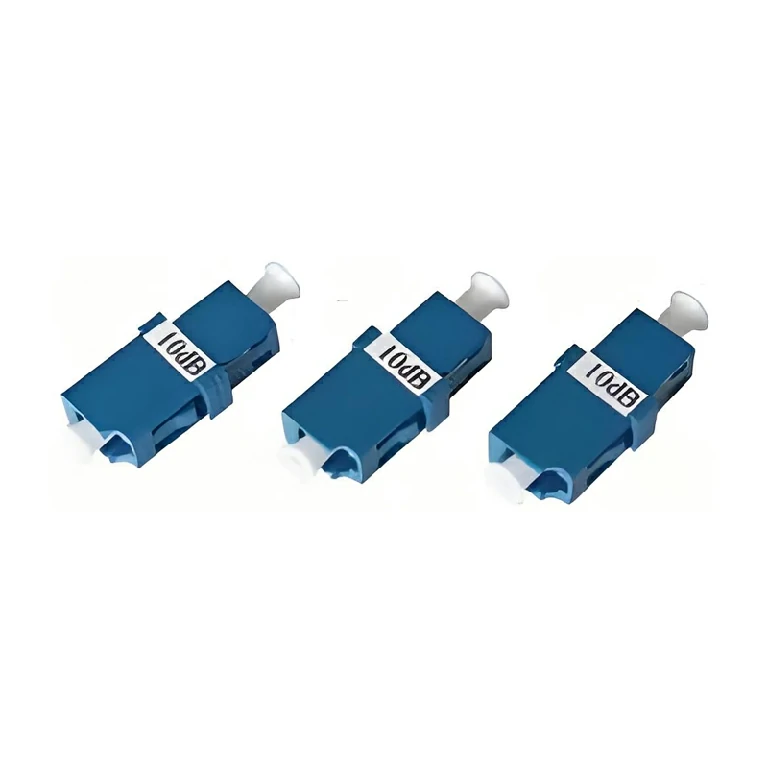
A family of fixed flange, male-female and in-line optical attenuators for setting receiver power by interface, wavelength and attenuation value.
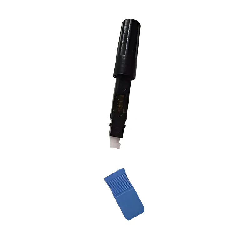
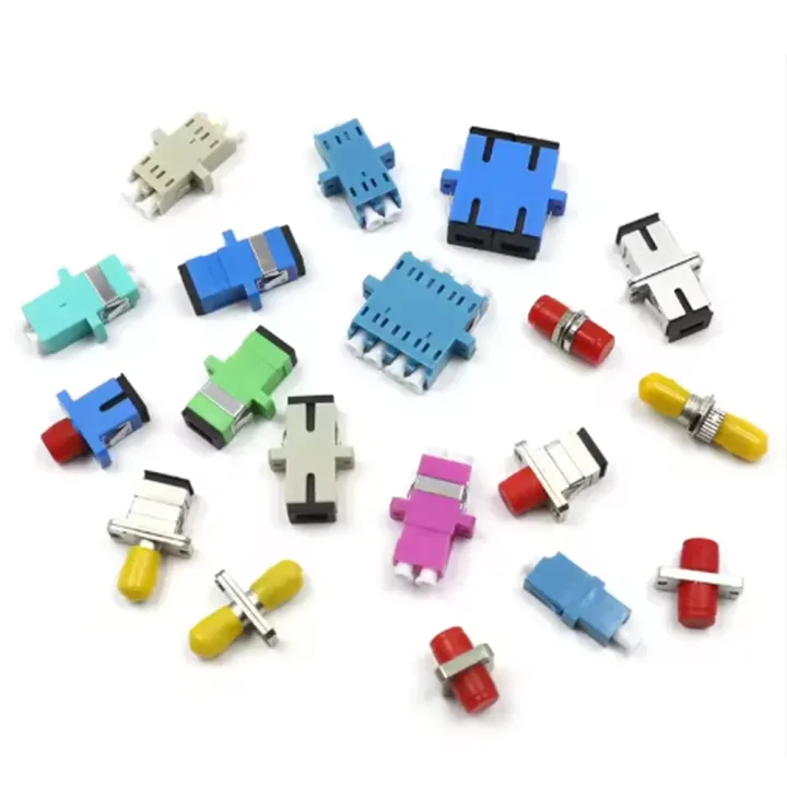
This Optical Attenuator family reduces excessive optical power to a defined level before the receiver. Available forms in the source include bulkhead/flange, male-female plug-in and in-line arrangements, with FC, LC, SC or ST interfaces and UPC or APC polish choices.
Fixed attenuation values from 1 to 30 dB are represented, while the current legacy table also includes an adjustable FC form. The required attenuation must come from the measured power budget; selecting a value only by product type can leave the receiver either overloaded or below sensitivity.
Provide wavelength, measured input power, receiver target, connector, polish, required attenuation and maximum optical power. Confirm whether a fixed passive device, a manually adjustable part or the separate electrically controlled MEMS product is intended. Temperature and power limits follow the selected part number, not the family name.
Huijue Group can review OEM/private-label attenuator assortments, custom labels and connectorized in-line assemblies. Customer samples or interface drawings can support fit checks; attenuation tolerance, housing, optical test, quantity and production feasibility need confirmation.
| Parameter | Adapter Type | Plug-Socket Type | In-Line Type | FC Variable Attenuator |
| Operating Wavelength (nm) | 1310 or 1550 | 1310 or 1550 | 1310 or 1550 or 850 | 1310 or 1550 |
| Operating Bandwidth (nm) | — | ±20 | ±20 | — |
| Return Loss (dB) | — | >40 | Single-Mode ≥50; Multi-Mode ≥30 | — |
| Attenuation Value (dB) | 5, 10, 15, 20 or Customized (0~25). Accuracy: ±0.5 for 1~2dB; ±0.75 for 3~7dB; ±10% for 8~25dB | Customizable | 0~25 | |
| Connector Type | FC/SC/ST, etc. | FC | ||
| Operating Temperature (℃) | -25~70 | -45~85 | — | |
| Maximum Bearing Power (mW) | 300 | |||
Keep interfaces clean and use the correct UPC or APC mating geometry. Verify the selected attenuator's temperature and optical-power rating for the installation; values from one housing style must not be transferred to another.
Buyer Questions
Answers specific to Optical Attenuator, MEMS Variable Optical Attenuator selection, configuration and purchasing.
Use the measured or calculated link budget and the receiver's allowable input range, then retain suitable engineering margin.
No. A fixed attenuator provides a set passive loss. A MEMS variable optical attenuator changes loss in response to an electrical drive.
No. Their end-face geometries differ and the attenuator must match the mating interface.
Use the deployment context to narrow the configuration before comparing dimensions, capacities and options.
Match splitter or WDM architecture to wavelength plan, ratio, package and insertion-loss targets.
Coordinate connector, polish, fiber grade, polarity and cable length across patching points.
Plan MPO/MTP trunks and harnesses around port mapping, breakout format and rack density.
Select splicing, cleaning and test tools for the connector types and measurements used on site.
Before quotation: confirm capacity, interfaces, installation environment, power conditions, quantity and required options.