
Passive optical distribution
Match splitter or WDM architecture to wavelength plan, ratio, package and insertion-loss targets.
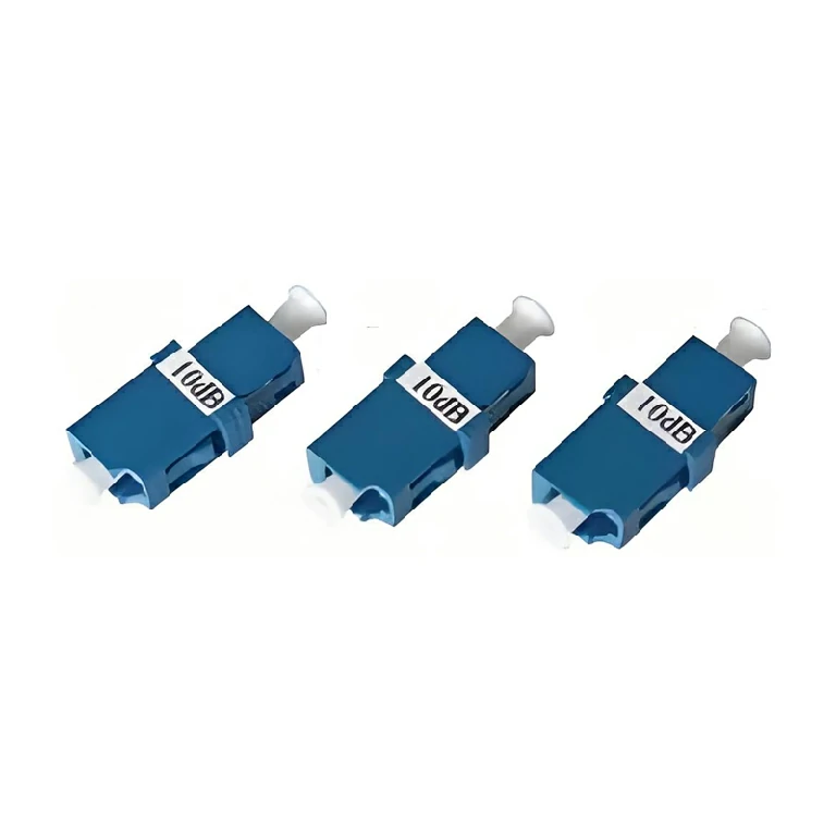
A compact in-line MEMS variable optical attenuator with at least 30 dB range, 0–5 V drive and a listed response time of 2 ms or less.
The MEMS Variable Optical Attenuator is an electrically controlled in-line component for changing optical power within a fiber path. A micro-electromechanical mechanism varies attenuation in response to the applied drive voltage, supporting dynamic leveling rather than one fixed loss value.
The current specification lists 1260–1650 nm operation, at least 30 dB attenuation range, normally open or normally closed forms, and continuous attenuation. Electrical control, optical connection and package integration must be treated as one design task.
Confirm wavelength, required attenuation range, default state, drive method, optical power, connectorization or bare-fiber leads, package and response requirement. The control circuit must respect the device drive range and the system's fail-state behavior.
Huijue Group can review drawing-based MEMS VOA packaging, fiber leads, connectors and private-label identification. A customer sample or control-interface drawing can support integration, but package tooling, electrical characterization, optical acceptance and production quantity require engineering approval.
| Parameter | Unit | Specification | Remarks |
| Operating Wavelength Range | nm | 1260-1650 | |
| Attenuation Type | — | Normally Open or Normally Closed | Continuous Attenuation |
| Attenuation Range | dB | ≥30 | |
| Insertion Loss¹ | dB | ≤0.7 | |
| Return Loss¹ | dB | ≥45 | |
| Response Time | ms | ≤2 | 10%~90% Optical Power |
| Driving Voltage | V | 0~5 | |
| Maximum Optical Power | mW | 300 | |
| Repeatability | dB | ≤0.1 |
Note: The above specifications do not include the loss of connector plugs.
Integrate the VOA in a protected assembly with strain relief and a controlled electrical drive. Do not exceed the listed optical power or voltage; final temperature and reliability limits must be confirmed for the ordered package.
Buyer Questions
Answers specific to MEMS Variable Optical Attenuator selection, configuration and purchasing.
It defines the device's optical state without the active control condition. Choose the fail-state behavior required by the system.
Connectorized leads can be reviewed, but connector type, polish, fiber length and package strain relief must be approved.
No. It is the listed analog drive range for the device; any digital control or closed-loop electronics are a separate system function.
Use the deployment context to narrow the configuration before comparing dimensions, capacities and options.
Match splitter or WDM architecture to wavelength plan, ratio, package and insertion-loss targets.
Coordinate connector, polish, fiber grade, polarity and cable length across patching points.
Plan MPO/MTP trunks and harnesses around port mapping, breakout format and rack density.
Select splicing, cleaning and test tools for the connector types and measurements used on site.
Before quotation: confirm capacity, interfaces, installation environment, power conditions, quantity and required options.