
Equipment rooms
Organize racks, pathways and service access around active network equipment.
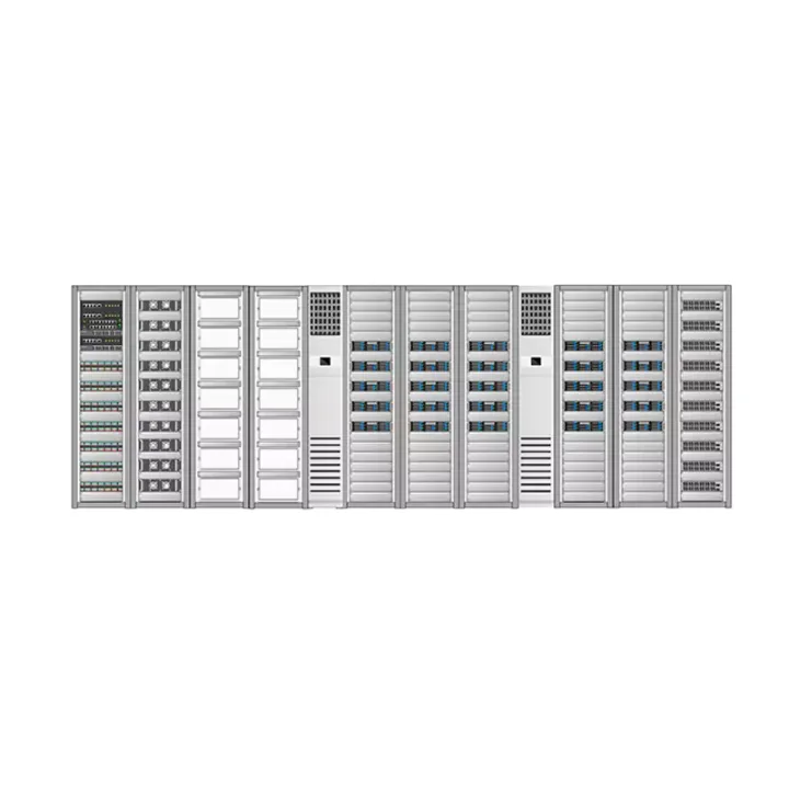
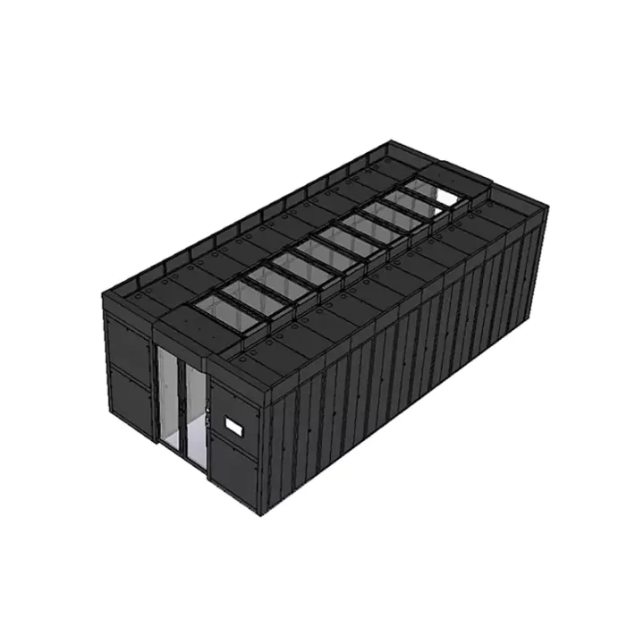
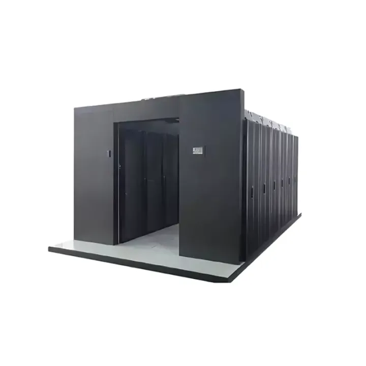
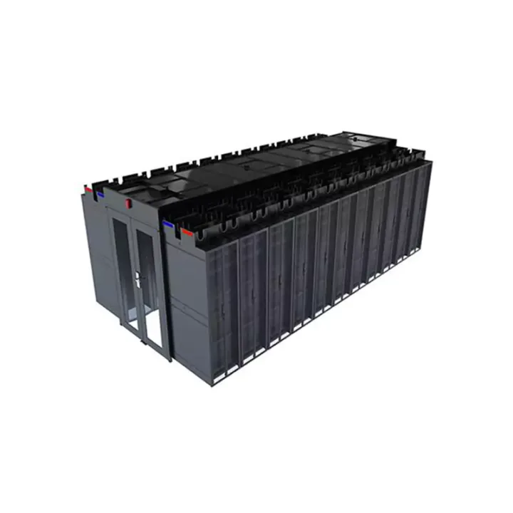
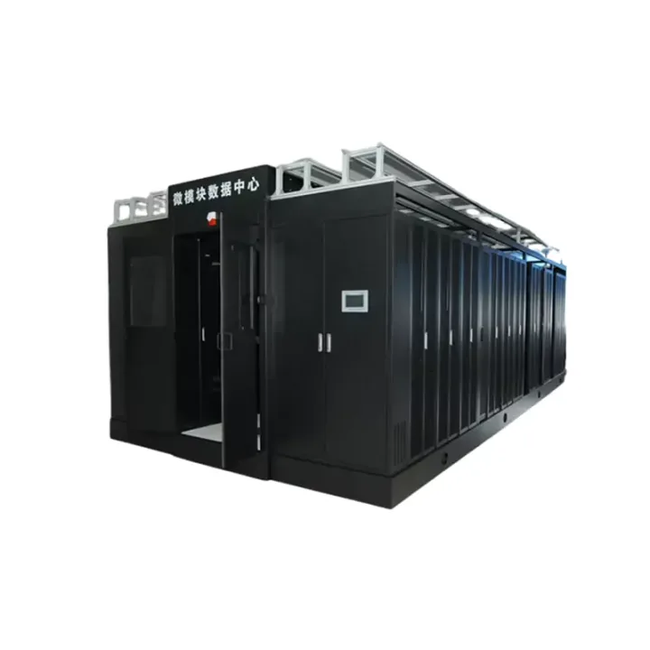
A double-row modular data-center architecture coordinating cabinets, cold-aisle containment, power, refrigeration and monitoring for larger groups of indoor IT equipment.
The HP1000 Multi-Rack Modular Data Center groups several infrastructure subsystems around multiple IT cabinets. Cabinet rows, supply and distribution, refrigeration, airflow containment, wiring and monitoring are brought into one planned module.
The reference configuration uses a double-row cold aisle arrangement. Its scale makes the equipment-room layout, upstream electrical service, heat rejection and staged growth important design inputs. Reference values describe a starting configuration and should be checked against the intended IT population.
Prepare a cabinet-by-cabinet load map and identify the redundancy required for power and cooling. The documented 6 kW per-cabinet reference does not mean every cabinet can be operated at that load simultaneously within the reference system. Agree operating and expansion loads before determining UPS, cooling and distribution capacities.
Confirm aisle width, door operation, bus and cable routes, battery autonomy, maintenance bypass and room service clearances.
Huijue Group can review a multi-rack modular data center for OEM delivery or private-label supply using room plans, subsystem drawings and sample interfaces. Architecture changes need engineering assessment of feasibility, tooling, integration tests, quantity and delivery scope.
Submit room geometry, cabinet counts and elevations, staged IT load, feed capacity, redundancy philosophy, autonomy target, cooling scheme, fire interfaces and monitoring requirements.
| HP1000 Multi-Rack Modular Data Center Reference Configuration | |||
|---|---|---|---|
| Cabinet system | Cooling System | ||
| Dimensions (H x W x D MM) | 2000(2200)X 600X 1200 | Rated AC input power supply | 380V AC 50Hz |
| System Layout / Configuration | Double-row cold aisle system (optional sliding door, sliding door) | Cooling capacity | 25kW * 4 (3 +1 redundancy) |
| Number of single cabinets | 10-40 | Rated Input Power | 7.5KW*4 |
| Capacity | 42U (46U) * number of cabinets | Rated current | 23.4A |
| Protection Rating | IP30 | Heating Capacity | 3KW*4 |
| Operating Temperature | -20℃~45℃ | Refrigerant | R410A |
| Installation | Concrete floor, raised floor | Sensible Heat Ratio (SHR) | ≥0.99 |
| Maximum load per cabinet | 6KW | Energy Efficiency Ratio | ≥3.2 |
| Supports maximum power consumption of IT load | 120KW | Air distribution | Front air supply, rear air return |
| IT cabinet bearing requirements | Static load 1500kg, dynamic load 1000kg | Installation | Inter-row installation |
| • Distribution System | Monitoring system | ||
| Lightning protection level | Class C, In 20ka, Imax40ka | Monitoring system | Support remote web interface access |
| Power Input | Single and dual channels optional | Local Interface | Standard 10-inch touch screen |
| Dual Power Switching System | Optional for 2-way input | Mobile O&M | Mobile App, SMS Alerts |
| UPS Capacity | 120KVA Modular UPS | Smoke detector | Optional |
| UPS Architecture | N +1 Module Redundancy | Water Leak Detection | Optional |
| Input Voltage | 380V Three Phase 3Ph + N + Pe | Temperature and humidity | Optional |
| Output voltage | 220V~240V AC 50Hz 380V~400V AC 50Hz | Access Control System | Optional |
| Output power factor | 0.9 | Video monitoring | Optional |
| Backup time | 15~30min | Fire Suppression System | |
| Maintenance Bypass | Standard | Fire Suppression Unit | Heptafluoropropane Cabinet-Type Fire Suppression Unit (Non-Piped) |
The published configuration lists IP30 and -20°C to 45°C operation. Installation on concrete or raised floors is described; floor loads, room ambient conditions and cooling connections require review.
Buyer Questions
Answers specific to HP1000 Multi-Rack Modular Data Center selection, configuration and purchasing.
The source lists four 25 kW units in a three-duty plus one-redundant arrangement. Confirm design temperatures, actual duty and failure behavior for the selected installation.
No. The 10–40 cabinet range and 120 kW IT-load reference must be reconciled with the actual rack loads, redundancy and power/cooling configuration.
Provide the future cabinet layout and load stages, including electrical and cooling expansion limits. Shared infrastructure and service access must accommodate those stages.
Use the deployment context to narrow the configuration before comparing dimensions, capacities and options.
Organize racks, pathways and service access around active network equipment.
Coordinate cabinet capacity, cable routes, airflow and planned expansion.
Package network equipment within compact distributed infrastructure sites.
Add capacity while accounting for existing racks, routes and maintenance space.
Before quotation: confirm capacity, interfaces, installation environment, power conditions, quantity and required options.