
Equipment rooms
Organize racks, pathways and service access around active network equipment.
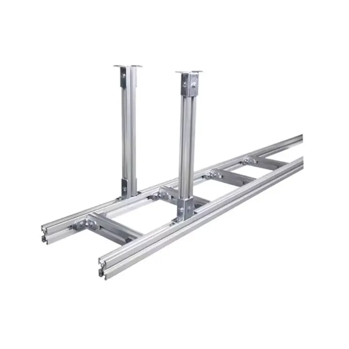
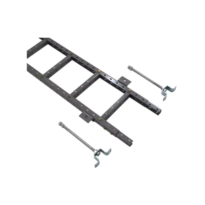
An open aluminum-alloy cable support in single- and double-layer arrangements, with 300–800 mm widths for organized cable routes in indoor communications rooms.
The source includes deformation observations under uniformly distributed loading across a 1.5 m test span. Those observations need to be interpreted with the actual support spacing and cable load rather than treated as a universal allowable load.
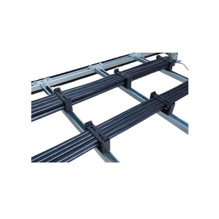
The Aluminum Alloy Cable Tray provides a visible, accessible route for optical, data and other room cables. Its open structure allows installers to place, secure and inspect cables along a defined path above or around communications equipment.
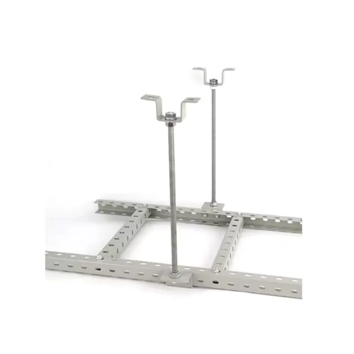
This record covers an indoor aluminum-alloy support family with single- and double-layer layouts. Select the number of layers from the cable grouping and room elevation, then check the supporting structure and loading for the complete route.
Estimate installed cable mass per metre and reserve width for growth. Check route elevation, hangers, wall or floor supports, intersections and equipment drops. Protect optical cable bend limits at changes in direction and entry points.
Huijue Group can assess aluminum tray runs for OEM or private-label projects using route drawings or a reference sample. Profile changes, connectors, tooling, load tests, quantities and delivery scope must be confirmed by engineering.
Provide route length, widths, layer arrangement, cable weights, support spacing, fixing surfaces, bends and branches, drop points and bonding requirements.
| S/N | Model | NAME | Type | Application scenarios | Width (mm) | Cross-sectional dimension (mm) | 1.5 m uniformly distributed load |
|---|---|---|---|---|---|---|---|
| 1 | HJ ZXJ21-L3A3 | Aluminum Alloy Cable Tray | Single-Tier | (indoor) | 300 | 31*45 | Deformation amount of 150kg 5mm 195kg Deformation 7mm |
| 2 | HJ ZXJ21-L3A4 | Aluminum Alloy Cable Tray | Single-Tier | (indoor) | 400 | 31*45 | Deformation amount of 150kg 5mm 195kg Deformation 7mm |
| 3 | HJ ZXJ21-L3A6 | Aluminum Alloy Cable Tray | Single-Tier | (indoor) | 600 | 31*45 | Deformation amount of 150kg 5mm 195kg Deformation 7mm |
| 4 | HJ ZXJ21-L3A8 | Aluminum Alloy Cable Tray | Single-Tier | (indoor) | 800 | 31*45 | Deformation amount of 150kg 5mm 195kg Deformation 7mm |
| 5 | HJ ZXJ22-L3A3 | Aluminum Alloy Cable Tray | Double-Tier | (indoor) | 300 | 31*45 | Deformation amount of 150kg 5mm 195kg Deformation 7mm |
| 6 | HJ ZXJ22-L3A4 | Aluminum Alloy Cable Tray | Double-Tier | (indoor) | 400 | 31*45 | Deformation amount of 150kg 5mm 195kg Deformation 7mm |
| 7 | HJ ZXJ22-L3A6 | Aluminum Alloy Cable Tray | Double-Tier | (indoor) | 600 | 31*45 | Deformation amount of 150kg 5mm 195kg Deformation 7mm |
| 8 | HJ ZXJ22-L3A8 | Aluminum Alloy Cable Tray | Double-Tier | (indoor) | 800 | 31*45 | Deformation amount of 150kg 5mm 195kg Deformation 7mm |
| S/N | Name | unit | quantity | REMARK | |||
| 1 | Longitudinal Rail | m | 2 | When the length is 1 meter and the width of the cable runway is ≥ 800 mm, the middle position of the cable runway is increased by 1 main rail | |||
| 2 | Cross Member | Cables | 4 | The length is the width of the cable runway, and the interval is 250mm. | |||
| 3 | piece | Number of places | 0.1 | Ground support, the length meets the height of the machine room | |||
| 4 | Hanging | Number of places | 0.67 | Length meets machine room height | |||
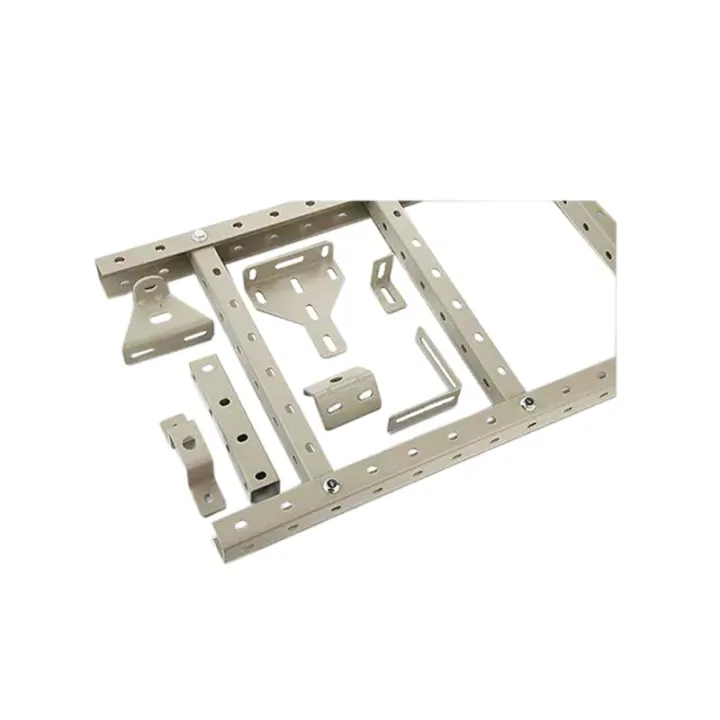
| 5 | Installation Accessories | Sleeve | 1 | Other parts (including but not limited to reinforcements, fasteners, grounding wires, etc.) required for complete installation of the wiring rack | |||
| S/N | Name | unit | quantity | REMARK | |||
| 1 | Longitudinal Rail | m | 4 | When the length is 1 meter and the width of the cable runway is ≥ 800 mm, the middle position of the cable runway is increased by 1 main rail | |||
| 2 | Cross Member | Cables | 8 | The length is the width of the cable runway, and the interval is 250mm. | |||
| 3 | piece | Number of places | 0.1 | Ground support, the length meets the height of the machine room | |||
| 4 | Hanging | Number of places | 0.67 | Length meets machine room height | |||
| 5 | Installation Accessories | Sleeve | 1 | Other parts (including but not limited to reinforcements, fasteners, grounding wires, etc.) required for complete installation of the wiring rack | |||
| 6 | Inter-Tier Support Posts | Cables | 1.33 | Length is double interval, double interval column height ≥ 250mm |
The listed aluminum variants are for indoor installation. Specify humidity, exposure and any contact with dissimilar metals when reviewing supports and finishes.
Buyer Questions
Answers specific to Aluminum Alloy Cable Tray selection, configuration and purchasing.
They describe a source test arrangement. The permitted span and deflection must be assessed for the selected profile, connections and actual distributed cable loading.
Use the cable grouping, separation plan, room height and maintenance access to define the layers. Include inter-layer space and support geometry in the route drawing.
Use the deployment context to narrow the configuration before comparing dimensions, capacities and options.
Organize racks, pathways and service access around active network equipment.
Coordinate cabinet capacity, cable routes, airflow and planned expansion.
Package network equipment within compact distributed infrastructure sites.
Add capacity while accounting for existing racks, routes and maintenance space.
Before quotation: confirm capacity, interfaces, installation environment, power conditions, quantity and required options.