
Central offices and equipment rooms
Organize high-capacity termination, cross-connection and patching with defined service access.
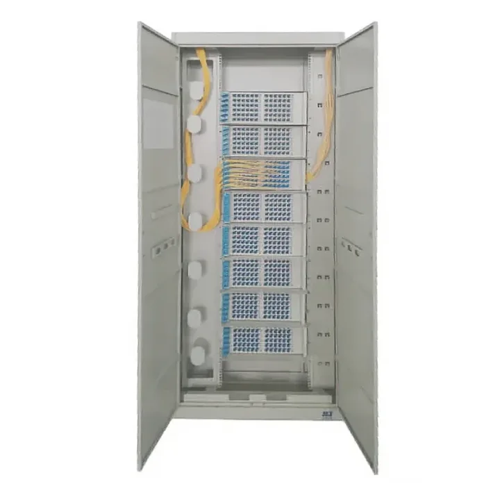
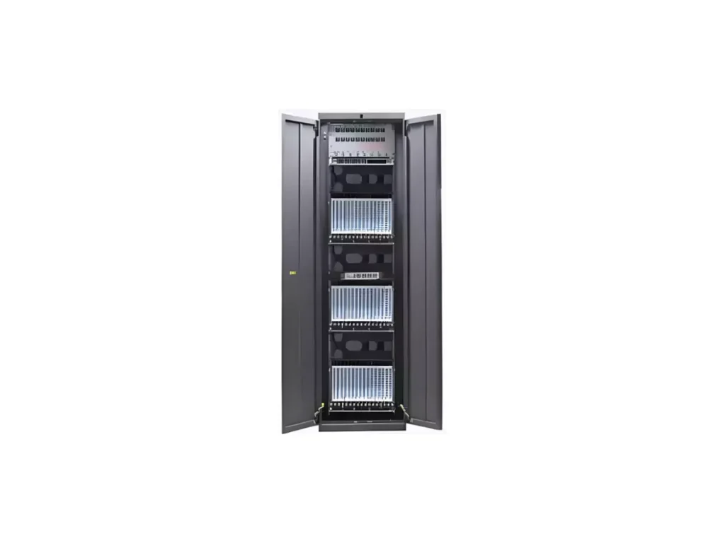
Equipment-Side ODF Frame provides structured optical termination, splicing and patching with a listed capacity of 504 cores for equipment-room fiber management.
The 2000 × 600 × 300 mm cold-rolled steel frame is listed at 504-core capacity using forty-two 12-core trays. Entry fixing, grounding and FC/SC/ST interface support are described.
The Equipment-Side ODF Frame provides an organized equipment-facing fiber handoff with integrated splice and connection units. A front-service arrangement permits wall-adjacent positioning while cable reserve and transmission-route assignments are managed within the frame.
Map equipment ports to tray positions and define patch-cord paths before population. Check front replacement access, room height and base support rather than assuming wall-adjacent means no service clearance.
Huijue Group can review OEM equipment-side frames, private labels and sample/drawing-based room interfaces. Frame tooling, layout feasibility, optical/structural tests, quantity and delivery scope require confirmation.
Send equipment-port inventory, 504-core allocation, cable/pigtail routes, connector polish and floor layout.
| Enclosure material | Cold-rolled steel sheet | Dimensions (mm) | 2000×600×300 | ||||
|---|---|---|---|---|---|---|---|
| Tray capacity | 504 cores | Weight (kg) | |||||
| Standard accessories | |||||||
| No. | Name | Unit | Qty | No. | Name | Unit | Qty |
| 1 | Frame | set | 1 | 6 | Cable fixing | set | 1 |
| 2 | Cable ties (nylon) | pc | 30 | 7 | Rubber dust seals | pc | 4 |
| 3 | Expansion bolts | pc | 4 | 8 | |||
| 4 | Splice protection sleeves | pc | 504 | 9 | |||
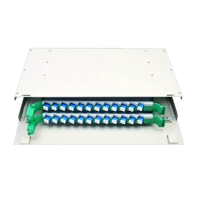
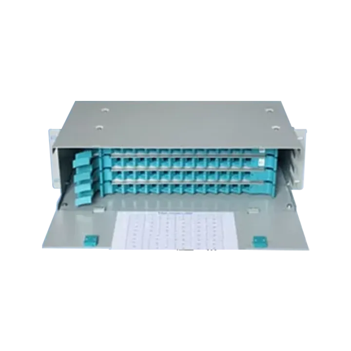
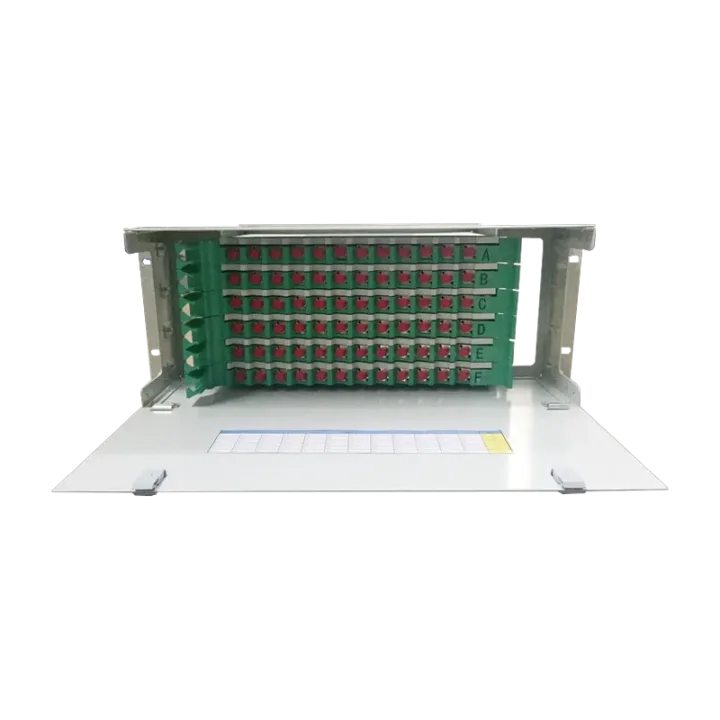
| 5 | 12-core integrated tray | pc | 42 | 10 | |||
| Optional accessories | |||||||
| No. | Name | Unit | Qty | No. | Name | Unit | Qty |
| 1 | SC pigtail | pc | 42 | 3 | SC adapter | pc | 504 |
| 2 | FC pigtail | pc | 42 | 4 | FC adapter | pc | 504 |
Equipment-facing ODF organization in communications rooms and access nodes with managed route scheduling.
Provide room conditions, floor support and earthing requirements for the completed frame and cable system.
Buyer Questions
Answers specific to Equipment-Side ODF Frame selection, configuration and purchasing.
Forty-two 12-core integrated trays are listed. Confirm installed adapters and any reserved positions.
Front access is described for wall-adjacent placement. Confirm door swing, cabling and installation clearances.
No. Select compatible adapters and pigtails for the actual equipment interfaces.
Use the deployment context to narrow the configuration before comparing dimensions, capacities and options.
Organize high-capacity termination, cross-connection and patching with defined service access.
Place splitter, terminal and distribution boxes at the correct feeder-to-drop transition.
Protect branching and splicing around cable entries, sealing, tray capacity and mounting method.
Reserve fibers, ports and internal routing space for staged subscriber or backbone growth.
Before quotation: confirm capacity, interfaces, installation environment, power conditions, quantity and required options.