
Core equipment rooms
Coordinate DC power, distribution, batteries and monitoring around communications loads.
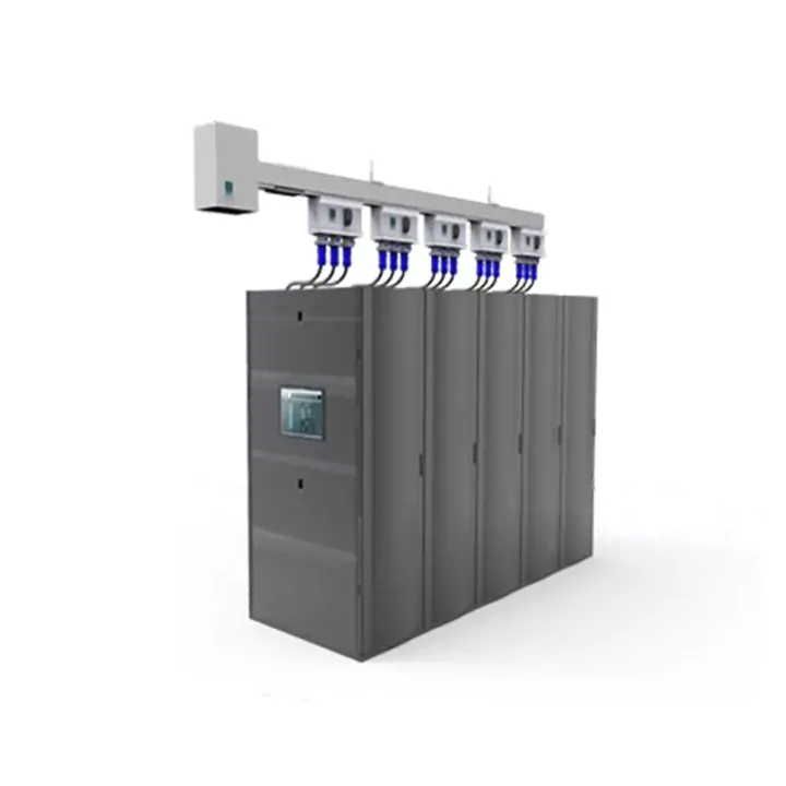
Modular busbar distribution for data-center rows, using reusable plug-in tap units and integrated circuit-monitoring provisions tailored to the facility layout.
The Data Center Smart Busbar replaces long point-to-point feeder runs with a modular bus architecture from the UPS output distribution cabinet toward rack-level PDU connections. Starting boxes, busbar sections and plug-in tap boxes create a distributed power route that can be extended or rearranged as row capacity changes.
Plug-in distribution units support phased deployment and redeployment without rebuilding the entire cable network. A dedicated communication path within the busbar can carry circuit measurements such as current and voltage to the facility monitoring layer, subject to the selected metering and protocol package.
A useful busbar schedule includes upstream UPS rating, system voltage, prospective short-circuit level, row length, rack count, tap-box ratings and planned future positions. Also specify overhead support conditions, aisle geometry, redundancy topology and the data interface expected by the DCIM or power-monitoring system.
Huijue Group can manufacture a project-specific busbar package and evaluate OEM/private-label identification, custom tap locations and assemblies based on drawings or a reference sample. Engineering must confirm conductor sizing, protection coordination, mechanical feasibility, tooling, temperature-rise tests, quantity and the order scope.
| Configuration | Project-specific; confirm requirements before quotation. |
Intended for controlled indoor technical spaces. Confirm ceiling/support capacity, clearances from cooling and fire systems, operating temperature, humidity, dust level and maintenance access before finalizing the route.
Buyer Questions
Answers specific to Data Center Smart Busbar selection, configuration and purchasing.
A modular busbar can reduce cable congestion and makes future rack connections easier to plan through plug-in tap boxes. Suitability depends on current rating, layout, fault level and maintenance strategy.
The architecture is designed for modular tap-off distribution, but live work policy, reserved capacity and the approved tap-box type govern any later addition. These points should be established in the original design.
Provide the single-line diagram, row length, current and voltage, rack/tap schedule, redundancy target, route drawing and monitoring requirements. A generic floor area is not enough to size the system.
Use the deployment context to narrow the configuration before comparing dimensions, capacities and options.
Coordinate DC power, distribution, batteries and monitoring around communications loads.
Use integrated or wall-mounted systems where equipment space is limited.
Match generation, storage and power conversion to load and autonomy requirements.
Combine grid, solar, battery or generator inputs around a defined operating strategy.
Before quotation: confirm capacity, interfaces, installation environment, power conditions, quantity and required options.