
Equipment rooms
Organize racks, pathways and service access around active network equipment.
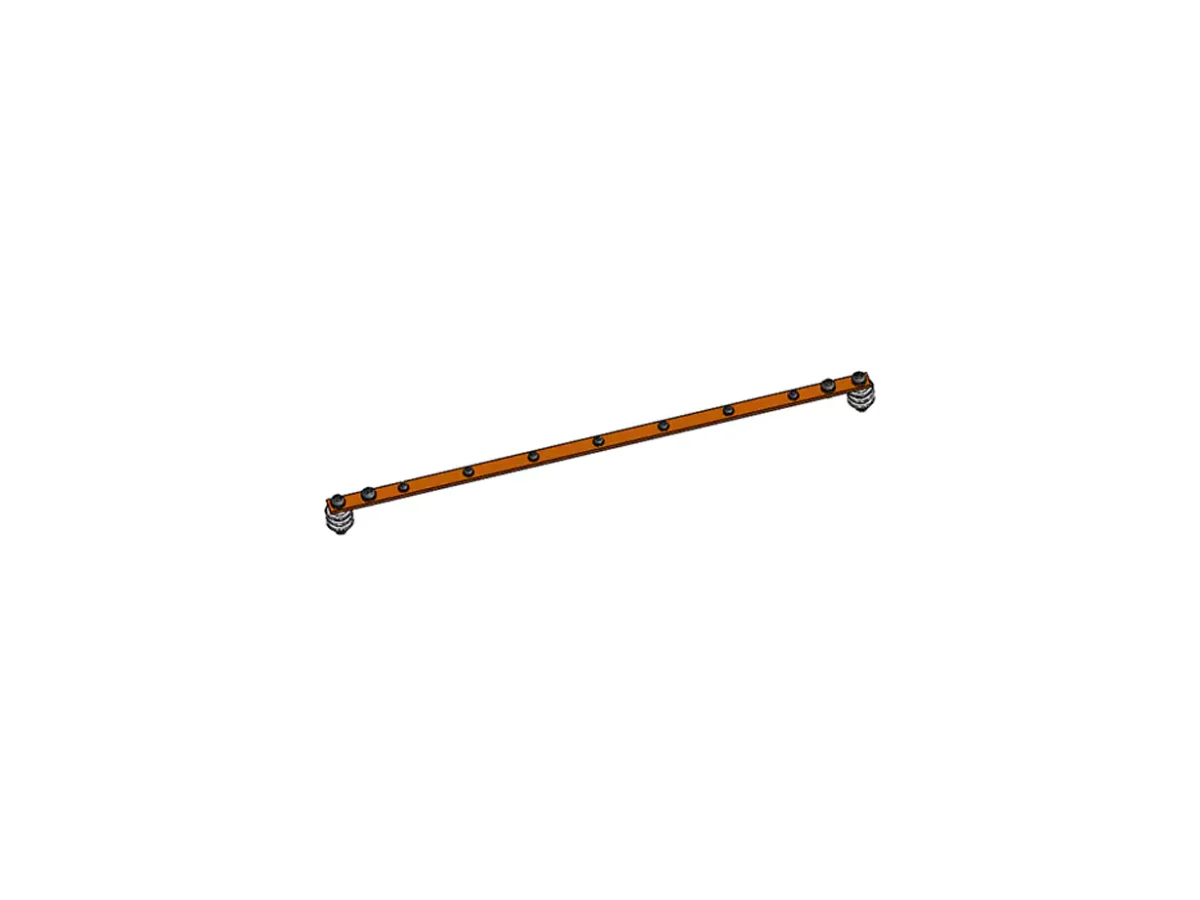
A nickel-plated T2 copper busbar with M8 connection studs for horizontal 19-inch or vertical protective bonding arrangements inside network and communications racks.
Rack Grounding Busbar provides a common connection point for protective bonding conductors inside a cabinet. It organizes the equipment bonding paths so that cable lugs and connection points can be planned as part of the rack installation.
The busbar is one component of the grounding system. Conductor sizing, continuity, fault-current considerations and connection to the site protective earth must be designed together; selecting a bar alone does not establish a complete grounding scheme.
Choose horizontal or vertical orientation from the rack layout and conductor routes. Specify bar length, connection quantity and spacing, lug dimensions and conductor sizes. The source dimensions do not establish a universal fault-current rating; the project designer must verify the complete bonding arrangement and applicable electrical requirements.
Huijue Group can assess OEM identification, private-label supply and a sample- or drawing-based busbar layout. Hole patterns, studs and mounting changes require engineering confirmation of tooling, electrical verification, quantity and delivery scope.
Provide orientation, rack height, bar length, connection counts, lug and conductor sizes, grounding design criteria, mounting details and required quantity.
| Material | T2 copper, purity ≥99.9% |
|---|---|
| Cross-sectional area | ≥35 mm² |
| Mounting | Horizontal 19-inch / vertical |
| Surface | Nickel-plated |
| Outgoing connection | M8 stud |
For indoor racks or inside a suitable protected cabinet. Consider the compatibility and exposure of copper, plating, lugs and mounting hardware within the actual installation.
Buyer Questions
Answers specific to Rack Grounding Busbar selection, configuration and purchasing.
No. It provides a local bonding point and must be connected within the site's designed protective-earth system.
Not by itself. The electrical design must consider conductor sizing, fault duration, connections and the full protective bonding path.
Send lug hole size, width, thickness and conductor size, together with the required connection spacing. The listed outgoing stud size is M8.
Use the deployment context to narrow the configuration before comparing dimensions, capacities and options.
Organize racks, pathways and service access around active network equipment.
Coordinate cabinet capacity, cable routes, airflow and planned expansion.
Package network equipment within compact distributed infrastructure sites.
Add capacity while accounting for existing racks, routes and maintenance space.
Before quotation: confirm capacity, interfaces, installation environment, power conditions, quantity and required options.