
Direct answer
Multi-vendor telecom site monitoring succeeds when every data point has a defined source, identifier, unit, accuracy, timestamp, update behavior, alarm limit and ownership. Begin with operational use cases rather than a protocol name: outage response, battery reserve, rectifier failure, cooling alarms, energy reporting and remote control each need specific points and actions. Then map device registers or objects through the gateway to the NOC or EMS, documenting scaling, quality flags, communication loss and time synchronization. SNMP, Modbus, REST or another interface does not by itself guarantee semantic interoperability. Control commands need stronger authorization, state confirmation and rollback rules than read-only telemetry. ITU monitoring guidance provides a useful information-model boundary, while final point lists and protocol files must match the exact supplied equipment.
Within the broader Integrated Telecom Site Energy workflow, this article focuses on telecom site energy monitoring interoperability: integrate power, battery, cooling and environmental data from multiple vendors into an auditable site-monitoring model. Confirm operational use cases and the evidence for the offered product before final engineering approval.
Scope boundary: This page addresses protocol, ownership and semantic interoperability across vendors. The earlier EMS points-list guide remains the detailed reference for naming individual power, battery, cooling and environmental points.

Ownership and data boundaries to establish first
Integrate power, battery, cooling and environmental data from multiple vendors into an auditable site-monitoring model. Start with the operating requirement and installation boundary, then separate system requirements from product claims so each supplier knows which evidence must accompany the offered configuration.
- Define the operating decisions that each monitored point or alarm must support.
- Choose site, equipment and point identifiers that remain stable across system changes.
- Map protocol objects with units, scaling, timestamps, quality and communication-loss behavior.
Define the operating decisions that each monitored point or alarm must support
Capture Operational use cases, then use Direct device integration as a practical comparison point: The NOC supports the device protocol and data model. Before approval, verify this point: Object mapping, security and firmware change control.
Choose site, equipment and point identifiers that remain stable across system changes
Capture Equipment and firmware inventory, then use Site gateway normalization as a practical comparison point: Several vendors or protocols share one site. Before approval, verify this point: Identifier model, buffering and time synchronization.
Map protocol objects with units, scaling, timestamps, quality and communication-loss behavior
Capture Protocol and register files, then use EMS-to-NOC integration as a practical comparison point: Energy optimization and network operations use separate platforms. Before approval, verify this point: Ownership, API contract and alarm duplication.
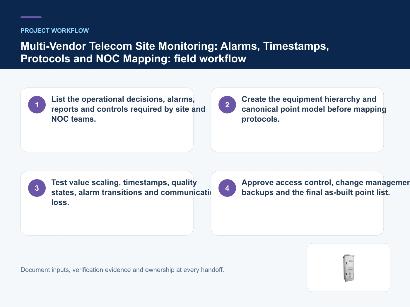
A point-to-platform interoperability workflow
- Step 1: List the operational decisions, alarms, reports and controls required by site and NOC teams. Record Operational use cases as an explicit input. Object mapping, security and firmware change control.
- Step 2: Create the equipment hierarchy and canonical point model before mapping protocols. Record Equipment and firmware inventory as an explicit input. Identifier model, buffering and time synchronization.
- Step 3: Test value scaling, timestamps, quality states, alarm transitions and communication loss. Record Protocol and register files as an explicit input. Ownership, API contract and alarm duplication.
Common mistakes to avoid
- Assuming that sharing a protocol means two devices use the same point semantics.
- Sending alarms without stable site, equipment and point identifiers or synchronized time.
Where multi-vendor monitoring commonly diverges
This table connects integrated site architecture, hybrid energy, batteries, BMS, monitoring, energy metrics and FAT/SAT handover to the decision on telecom site energy monitoring interoperability. It is a decision aid rather than a universal performance table: exact capacity, environmental class, electrical or optical limits and certifications must come from the selected model, applicable project documents and verifiable test evidence.
| Option or input | When it fits | What must be verified |
|---|---|---|
| Direct device integration | The NOC supports the device protocol and data model | Object mapping, security and firmware change control |
| Site gateway normalization | Several vendors or protocols share one site | Identifier model, buffering and time synchronization |
Reference point: ITU-T L.1395: Monitoring and control interface for power, cooling and building environment systems in telecommunication networks and ITU-T L.1350: Energy efficiency metrics and measurement for telecommunication facilities frame the terminology or method used for this telecom site energy monitoring interoperability comparison. They do not approve a product configuration; apply the edition named by the contract and local authority.
Relevant products from our communications portfolio
The products below connect the telecom site energy monitoring interoperability decision to real catalogue families and verified site photography. They are starting points, not a claim that every configuration described here is a standard stock item; confirm model, interface, rating, drawing and testing scope with the project team.
- Telecom Site Energy Management System (EMS) — use this product page as a configuration reference when you define the operating decisions that each monitored point or alarm must support. Confirm the offered model, interfaces, drawings and available evidence before quotation.
- Indoor Hybrid Telecom Energy Cabinet — use this product page as a configuration reference when you choose site, equipment and point identifiers that remain stable across system changes. Confirm the offered model, interfaces, drawings and available evidence before quotation.
- Tower Company Outdoor Power Cabinet — use this product page as a configuration reference when you map protocol objects with units, scaling, timestamps, quality and communication-loss behavior. Confirm the offered model, interfaces, drawings and available evidence before quotation.
- Outdoor Integrated Power Supply — use this product page as a configuration reference when you separate read-only monitoring from authenticated remote-control functions and approvals. Confirm the offered model, interfaces, drawings and available evidence before quotation.
For adjacent configurations, browse Telecom Power & Site Energy and compare those options against the telecom site energy monitoring interoperability inputs above, including operational use cases.
What to include in the RFQ or design input
For telecom site energy monitoring interoperability, a complete request reduces back-and-forth and prevents a catalogue image from being mistaken for a verified configuration. Record the following fields, identify which values are mandatory or provisional and attach route, interface or layout drawings where relevant.
- Operational use cases
- Equipment and firmware inventory
- Protocol and register files
- Point names and units
- Timestamp and synchronization method
Questions engineers and buyers ask
How should direct device integration be evaluated for telecom site energy monitoring interoperability?
Use the noc supports the device protocol and data model as the operating context, record operational use cases, and verify object mapping, security and firmware change control for the exact offered configuration.
Sources and standards
The references below define terminology, scope or test methods relevant to telecom site energy monitoring interoperability. They do not certify an offered product; confirm the edition adopted by the contract and destination authority.
- ITU-T L.1395: Monitoring and control interface for power, cooling and building environment systems in telecommunication networks (2025 edition). Use it to verify the terminology and scope relevant to telecom site energy monitoring interoperability; the source does not certify a specific offered product.
- ITU-T L.1350: Energy efficiency metrics and measurement for telecommunication facilities (In force; reviewed 2026-10-16). Use it to verify the terminology and scope relevant to telecom site energy monitoring interoperability; the source does not certify a specific offered product.
- ITU-T L.1351: Energy efficiency metrics and measurement methods for telecommunication network infrastructure (In force; reviewed 2026-10-16). Use it to verify the terminology and scope relevant to telecom site energy monitoring interoperability; the source does not certify a specific offered product.
Source review: Links and cited editions for telecom site energy monitoring interoperability were checked on 2026-10-16. Confirm the edition adopted by the project contract and the authority having jurisdiction.
Related guidance
Weak-Grid vs Off-Grid Telecom Power: Choosing Grid, PV, Battery and Generator Roles • Telecom Site EMS Points List • Telecom Battery Backup Runtime: Calculated Autonomy vs Site Verification
Prepare a telecom site energy monitoring interoperability configuration for review
Send operational use cases, equipment and firmware inventory, protocol and register files, point names and units, quantity and delivery destination. Huijue Group can review the configuration boundary and identify the drawings or evidence needed for a factory quotation.
——END——