
Direct answer
Telecom DC distribution protection should isolate a failed branch without unnecessarily removing healthy critical loads. Start with the source fault capability, conductor size and length, equipment input current and inrush, branch criticality, disconnecting method and the ratings of devices specifically intended for the DC duty. Then compare upstream and downstream operating characteristics, voltage drop, interrupting capacity, polarity, temperature effects and access for maintenance. A breaker or fuse selected only from steady-state current may not protect the cable or coordinate with the upstream device. Document normal, overload and short-circuit assumptions and keep spare ways within the thermal and busbar design. IEC assembly and converter standards provide relevant frameworks, but the final protection study and evidence must match the offered cabinet, devices, wiring and destination requirements.
Within the broader Telecom DC Power Engineering workflow, this article focuses on telecom DC distribution protection: coordinate branch protection with conductors, loads and upstream devices in a telecom DC distribution system. Confirm dc voltage range and the evidence for the offered product before final engineering approval.
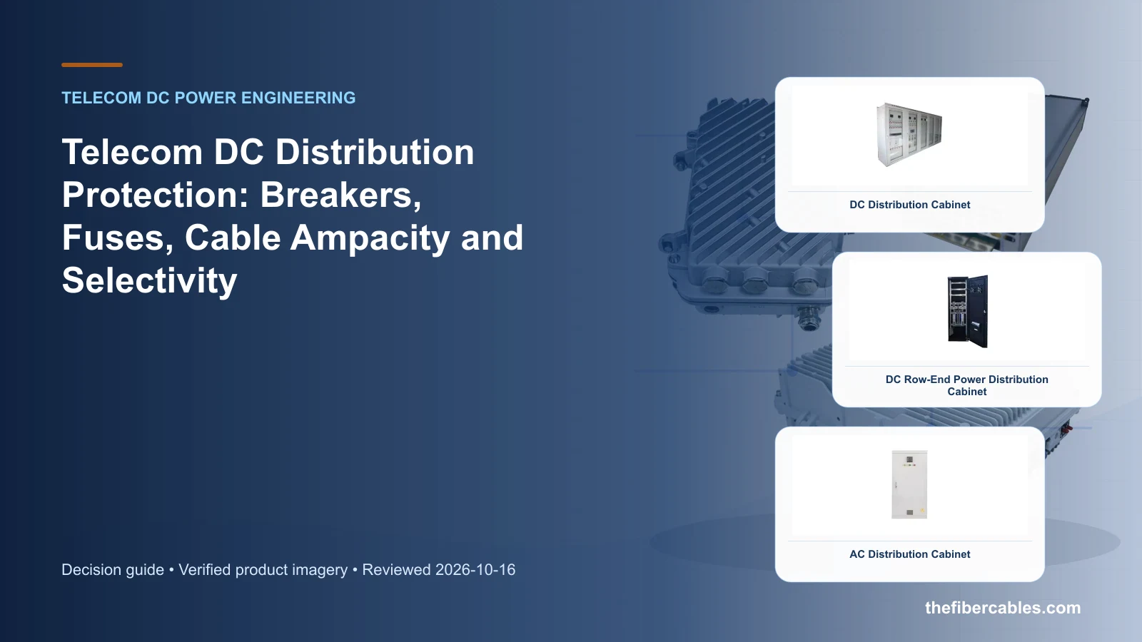
Fault and load inputs required for coordination
Coordinate branch protection with conductors, loads and upstream devices in a telecom DC distribution system. Start with the operating requirement and installation boundary, then separate system requirements from product claims so each supplier knows which evidence must accompany the offered configuration.
- Establish available fault current and the approved DC voltage at each distribution level.
- Match each protective device to conductor ampacity, load current, inrush and isolation duty.
- Review upstream and downstream operating curves or manufacturer coordination data.
- Reserve future circuits only after checking busbar, enclosure and thermal capacity.
Establish available fault current and the approved DC voltage at each distribution level
Capture DC voltage range, then use Fuse-protected branch as a practical comparison point: Simple defined load with an approved replacement practice. Before approval, verify this point: DC rating, clearing behavior and spare fuse control.
Match each protective device to conductor ampacity, load current, inrush and isolation duty
Capture Source fault-current basis, then use DC breaker branch as a practical comparison point: Resettable isolation and status indication are required. Before approval, verify this point: Polarity, interrupting rating and trip characteristic.
Review upstream and downstream operating curves or manufacturer coordination data
Capture Load and inrush schedule, then use Mixed distribution levels as a practical comparison point: Main and sub-distribution devices operate in series. Before approval, verify this point: Selectivity evidence, fault level and cable protection.
Reserve future circuits only after checking busbar, enclosure and thermal capacity
Capture Cable sizes and lengths, then use Fuse-protected branch as a practical comparison point: Simple defined load with an approved replacement practice. Before approval, verify this point: DC rating, clearing behavior and spare fuse control.
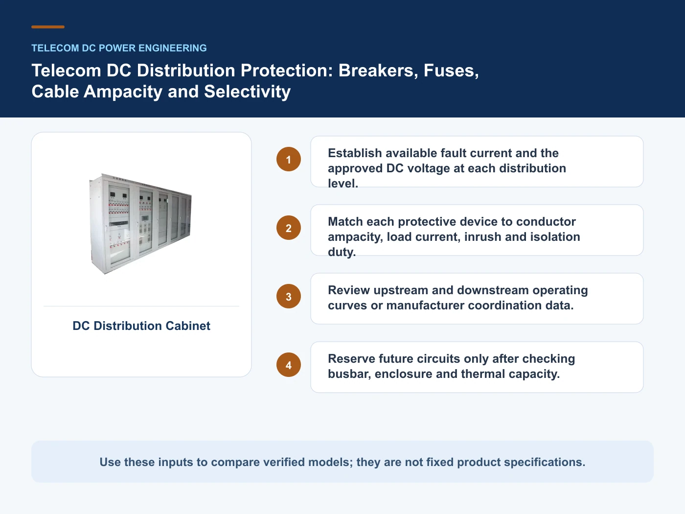
Relevant products from our communications portfolio
The products below connect the telecom DC distribution protection decision to real catalogue families and verified site photography. They are starting points, not a claim that every configuration described here is a standard stock item; confirm model, interface, rating, drawing and testing scope with the project team.
- DC Distribution Cabinet — use this product page as a configuration reference when you establish available fault current and the approved DC voltage at each distribution level. Confirm the offered model, interfaces, drawings and available evidence before quotation.
- DC Row-End Power Distribution Cabinet — use this product page as a configuration reference when you match each protective device to conductor ampacity, load current, inrush and isolation duty. Confirm the offered model, interfaces, drawings and available evidence before quotation.
- AC Distribution Cabinet — use this product page as a configuration reference when you review upstream and downstream operating curves or manufacturer coordination data. Confirm the offered model, interfaces, drawings and available evidence before quotation.
- Highway Power Distribution Control Box — use this product page as a configuration reference when you reserve future circuits only after checking busbar, enclosure and thermal capacity. Confirm the offered model, interfaces, drawings and available evidence before quotation.
For adjacent configurations, browse Telecom Power & Site Energy and compare those options against the telecom DC distribution protection inputs above, including dc voltage range.
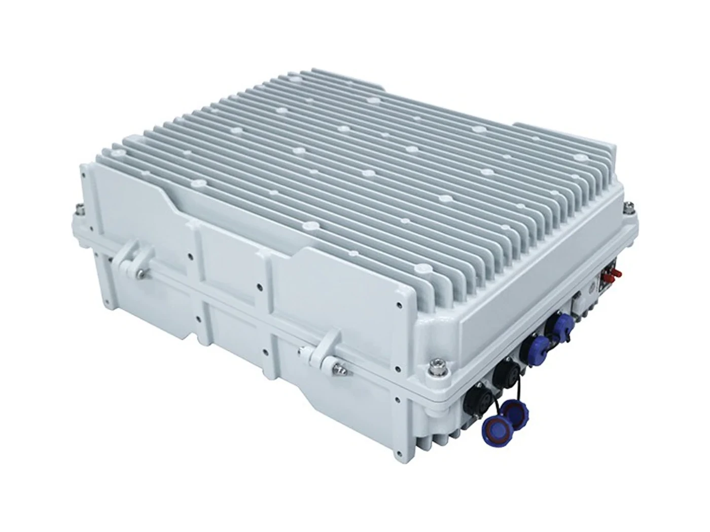
Protective-device choices and proof boundaries
This table connects -48 V plant retrofit, rectifiers, recharge, disconnect logic, protection, distribution and equipment interfaces to the decision on telecom DC distribution protection. It is a decision aid rather than a universal performance table: exact capacity, environmental class, electrical or optical limits and certifications must come from the selected model, applicable project documents and verifiable test evidence.
| Option or input | When it fits | What must be verified |
|---|---|---|
| Fuse-protected branch | Simple defined load with an approved replacement practice | DC rating, clearing behavior and spare fuse control |
| DC breaker branch | Resettable isolation and status indication are required | Polarity, interrupting rating and trip characteristic |
| Mixed distribution levels | Main and sub-distribution devices operate in series | Selectivity evidence, fault level and cable protection |
Reference point: ETSI EN 300 132-2: Power supply interface at the input of ICT equipment — -48 V direct current and IEC 61439-1: Low-voltage switchgear and controlgear assemblies — General rules frame the terminology or method used for this telecom DC distribution protection comparison. They do not approve a product configuration; apply the edition named by the contract and local authority.
A protection study that follows source, cable and load
- Step 1: Create a branch schedule with load, cable, route, criticality and isolation requirements. Record DC voltage range as an explicit input. DC rating, clearing behavior and spare fuse control.
- Step 2: Determine the fault and operating conditions at the source and each downstream point. Record Source fault-current basis as an explicit input. Polarity, interrupting rating and trip characteristic.
- Step 3: Select DC-rated devices and document conductor protection plus upstream coordination. Record Load and inrush schedule as an explicit input. Selectivity evidence, fault level and cable protection.
- Step 4: Verify labels, polarity, torque, alarms and trip or continuity checks during acceptance. Record Cable sizes and lengths as an explicit input. DC rating, clearing behavior and spare fuse control.
Common mistakes to avoid
- Applying an AC device rating to a DC circuit without suitable evidence.
- Sizing a branch device from steady current while ignoring cable limits and inrush.
- Adding spare breakers without checking busbar loading and enclosure temperature rise.
What to include in the RFQ or design input
For telecom DC distribution protection, a complete request reduces back-and-forth and prevents a catalogue image from being mistaken for a verified configuration. Record the following fields, identify which values are mandatory or provisional and attach route, interface or layout drawings where relevant.
- DC voltage range
- Source fault-current basis
- Load and inrush schedule
- Cable sizes and lengths
- Protective device schedule
- Selectivity requirement
Questions engineers and buyers ask
How should fuse-protected branch be evaluated for telecom DC distribution protection?
Use simple defined load with an approved replacement practice as the operating context, record dc voltage range, and verify dc rating, clearing behavior and spare fuse control for the exact offered configuration.
Which project input can change the telecom DC distribution protection decision?
Establish available fault current and the approved DC voltage at each distribution level. Recheck that decision when source fault-current basis or load and inrush schedule changes.
Sources and standards
These sources support the method and vocabulary used in this guide. They are not a substitute for project requirements or evidence tied to the exact telecom DC distribution protection configuration.
- ETSI EN 300 132-2: Power supply interface at the input of ICT equipment — -48 V direct current (V2.8.1, 2024). Use it to verify the terminology and scope relevant to telecom DC distribution protection; the source does not certify a specific offered product.
- IEC 61439-1: Low-voltage switchgear and controlgear assemblies — General rules (2020, Ed. 3). Use it to verify the terminology and scope relevant to telecom DC distribution protection; the source does not certify a specific offered product.
- IEC 62477-1: Safety requirements for power electronic converter systems and equipment (2022, Ed. 2). Use it to verify the terminology and scope relevant to telecom DC distribution protection; the source does not certify a specific offered product.
Source review: Links and cited editions for telecom DC distribution protection were checked on 2026-10-16. Confirm the edition adopted by the project contract and the authority having jurisdiction.
Related guidance
Brownfield -48 V Telecom Power Retrofit: Capacity, Interfaces and Cutover Planning • LVD vs BLVD in Telecom DC Power Systems: Load Priority and Battery Protection • -48 V DC Earthing and Return Architectures for Telecom Sites
Prepare a telecom DC distribution protection configuration for review
For a project review, provide dc voltage range, source fault-current basis, load and inrush schedule, cable sizes and lengths. The response can separate standard options, customization points and information still required before quotation.
——END——