
Core equipment rooms
Coordinate DC power, distribution, batteries and monitoring around communications loads.
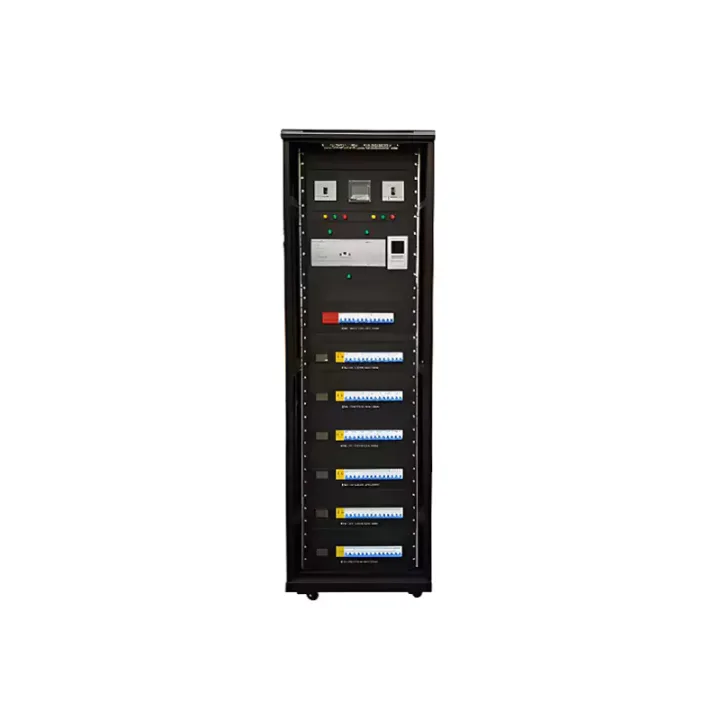
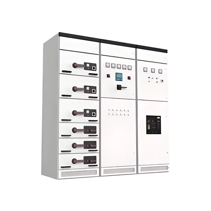
Automatic transfer switch cabinet for supervised changeover between primary and standby AC sources, with return-to-normal operation when mains recovers.
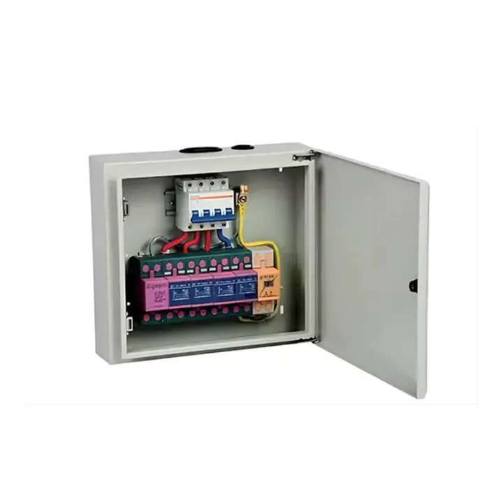
The Automatic Transfer Switch (ATS) Cabinet maintains supply continuity by monitoring two AC sources and transferring the connected load when the preferred source fails or moves outside the accepted condition. When the primary supply returns and satisfies the configured criteria, the system can transfer back automatically.
The cabinet combines the transfer device, controls, protective equipment and clear operating indication in one assembly. It is applicable where utility/utility or utility/generator source changeover must be automated but still coordinated with downstream equipment and site operating procedures.
State both source voltages, phases, frequency, neutral arrangement, rated current and prospective fault level. Transfer timing, source-priority logic, generator start contact, manual/bypass needs and downstream load tolerance must be defined. Confirm whether switching the neutral is required by the earthing scheme.
Huijue Group can assess OEM/private-label ATS cabinets from an approved changeover drawing or reference sample. Engineering confirms topology feasibility, panel tooling, interlocks, components, functional tests, order quantity and delivery responsibilities for generator/control integration.
| Operating temperature | -5℃~55℃ |
|---|---|
| Storage temperature | -20℃~+55℃ |
| Operating relative humidity | ≤80% (at +30℃) |
| Storage relative humidity | ≤90%~96% (40℃±2℃) |
| Atmospheric pressure | 65~110 kPa |
| Product dimensions | (400-1200) W × (600-1200) D × 2200 H |
The published operating range is −5°C to 55°C with up to 80% RH at 30°C. Identify indoor/outdoor placement, ventilation, altitude, cable entry and maintenance access.
Buyer Questions
Answers specific to Automatic Transfer Switch (ATS) Cabinet selection, configuration and purchasing.
Request the required generator start/stop signal explicitly. Engineering must confirm the selected controller supports the contact logic and the generator interface; automatic source transfer alone does not establish this function.
Provide the required transfer/return timing and the load's interruption tolerance. Engineering must check the adjustment range and sequence against the selected transfer controller.
Manual control or maintenance-bypass requirements should be declared at the design stage. The safe switching and interlock arrangement depends on the selected topology.
Use the deployment context to narrow the configuration before comparing dimensions, capacities and options.
Coordinate DC power, distribution, batteries and monitoring around communications loads.
Use integrated or wall-mounted systems where equipment space is limited.
Match generation, storage and power conversion to load and autonomy requirements.
Combine grid, solar, battery or generator inputs around a defined operating strategy.
Before quotation: confirm capacity, interfaces, installation environment, power conditions, quantity and required options.