
Core equipment rooms
Coordinate DC power, distribution, batteries and monitoring around communications loads.
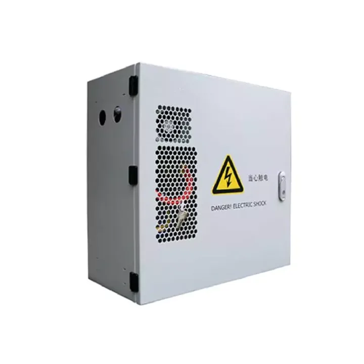
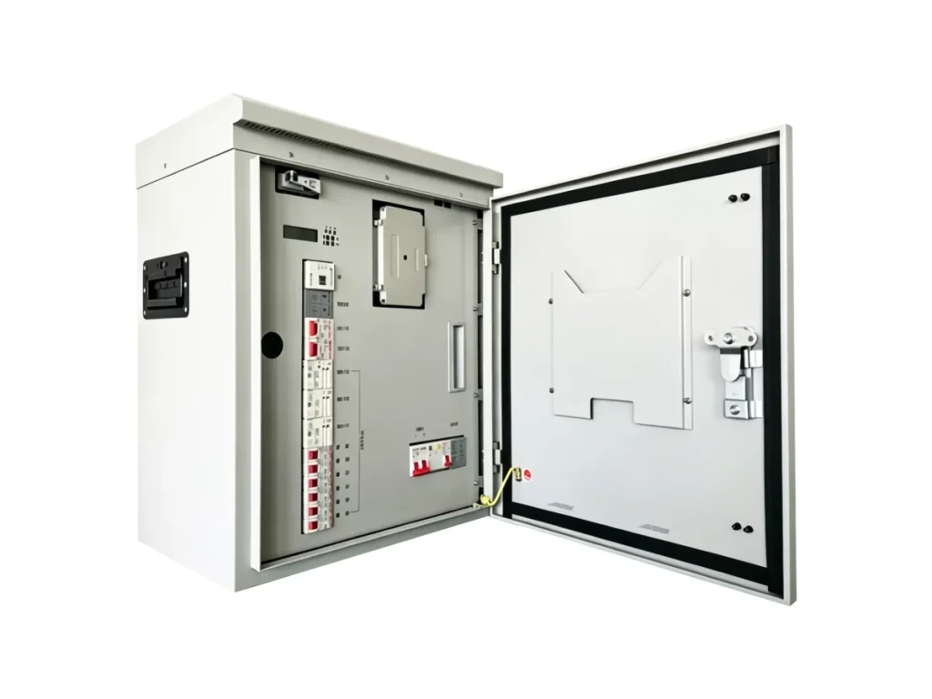
200 A or 300 A wall-mounted telecom power systems combining 50 A rectifier modules, configurable DC load branches and protected battery connections.
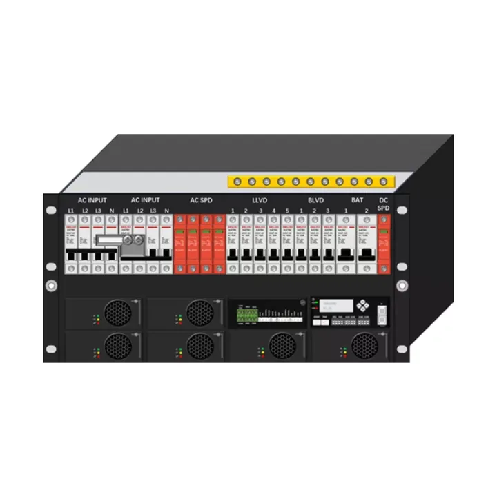
The Wall-Mounted Power System consolidates rectification and distribution where floor space is limited. The 200 A platform accepts up to four 50 A modules; the 300 A platform accepts up to six. Both use a documented 220 V AC input and provide two 125 A battery circuits, with load branches configured for the equipment schedule.
Wall loading and service access are part of selection. The 200 A assembly measures 480 × 270 × 465 mm and weighs 24 kg with four modules; the 300 A assembly measures 550 × 280 × 550 mm and weighs 38 kg with six modules.
Allow rectifier capacity for battery recharge and any module redundancy. Specify the load-disconnect groups and branch currents rather than selecting only a total output. Check the wall structure, anchors, cable bend space and working clearance against the fully equipped assembly weight.
Huijue Group can review a wall-power schedule with OEM labels or private-label documentation, and assess drawings or sample assemblies. Feasibility of branch changes, mounting tooling, protection tests, order quantity and the delivered accessories must be confirmed by engineering.
Provide 200 A or 300 A requirement, live load and recharge current, AC input details, branch/disconnect schedule, battery data, wall drawing and optional maintenance circuits.
| AC input | 220 Vac |
|---|---|
| System max. capacity | 300A (up to 6 × 50A rectifier modules) |
| Load branches | Standard: load disconnect 100A×3 (breakers), battery disconnect 100A×2 (breakers) (load branches configurable per need, max. 10 branches) |
| Battery branches | 125A ×2 circuits (breakers) |
| AC input switch | 125AP × 1 circuit (single-phase) |
| AC surge protection | 20 kA (Max 40 kA) |
| Optional configuration | |
| AC output branch | 10A×1 |
| AC maintenance outlet | 10A×1 |
| Temperature sensing cable | Ambient temperature sensor cable ×1 |
| DC surge protection | 15 kA×1 |
| Dimensions & weight | |
| Dimensions (mm) | 550 (W)×280 (D)×550 (H) |
| Weight (kg) | 38 (including 6 rectifier modules) |
| 200A Basic Configuration | |
| AC input | 220 Vac |
| System max. capacity | 200A (up to 4 × 50A rectifier modules) |
| Load branches | Load disconnect: 100A×1, 63A×2, 32A×2, 20A×2 (breakers); battery disconnect: 20A×1, 10A×2 (breakers) (load branches configurable per need, max. 10 branches) |
| Battery branches | 125A ×2 circuits (breakers) |
| AC input switch | 80AP × 1 circuit |
| AC surge protection | 20 kA (Max 40 kA) |
| Optional configuration | |
| AC output branch | 10A×1 |
| AC maintenance outlet | 10A×1 |
| Temperature sensing cable | Ambient temperature sensor cable ×1 |
| DC surge protection | 15 kA×1 |
| Dimensions & weight | |
| Dimensions (mm) | 480 (W)×270 (D)×465 (H) |
| Weight (kg) | 24 (including 4 rectifier modules) |
Confirm host-room cooling, humidity, wall capacity and cable routing. A wall-mounted format by itself does not establish outdoor weather protection.
Buyer Questions
Answers specific to Wall-Mounted Power System selection, configuration and purchasing.
Its maximum configuration is six 50 A modules. The installed quantity depends on the required load, battery charging and redundancy strategy.
Load branches can be reviewed up to ten, subject to branch-device size, busbar capacity and wiring space. Send the required current for each circuit.
The listed equipped weights are 24 kg for the four-module 200 A system and 38 kg for the six-module 300 A system. The installer must also account for cables, anchors and the final ordered configuration.
Use the deployment context to narrow the configuration before comparing dimensions, capacities and options.
Coordinate DC power, distribution, batteries and monitoring around communications loads.
Use integrated or wall-mounted systems where equipment space is limited.
Match generation, storage and power conversion to load and autonomy requirements.
Combine grid, solar, battery or generator inputs around a defined operating strategy.
Before quotation: confirm capacity, interfaces, installation environment, power conditions, quantity and required options.