
Direct answer
A telecom power system is more than a rectifier rating. The design must connect the AC source, protection, conversion, DC bus, branch circuits, batteries, monitoring and load interfaces under normal and abnormal conditions. Start with a measured load schedule and required autonomy, then state input conditions, voltage interface, redundancy, charging demand, protection coordination, environmental limits and acceptance tests.
This pillar guide connects AC input, DC interfaces, rectifier capacity, branch protection, redundancy and backup. Use it to define project inputs before narrowing to a product family.
System boundaries to define before product selection
Define the complete power path, interfaces, redundancy and backup boundaries. Start with the operating requirement and installation boundary, then separate system requirements from product claims so each supplier knows which evidence must accompany the offered configuration.
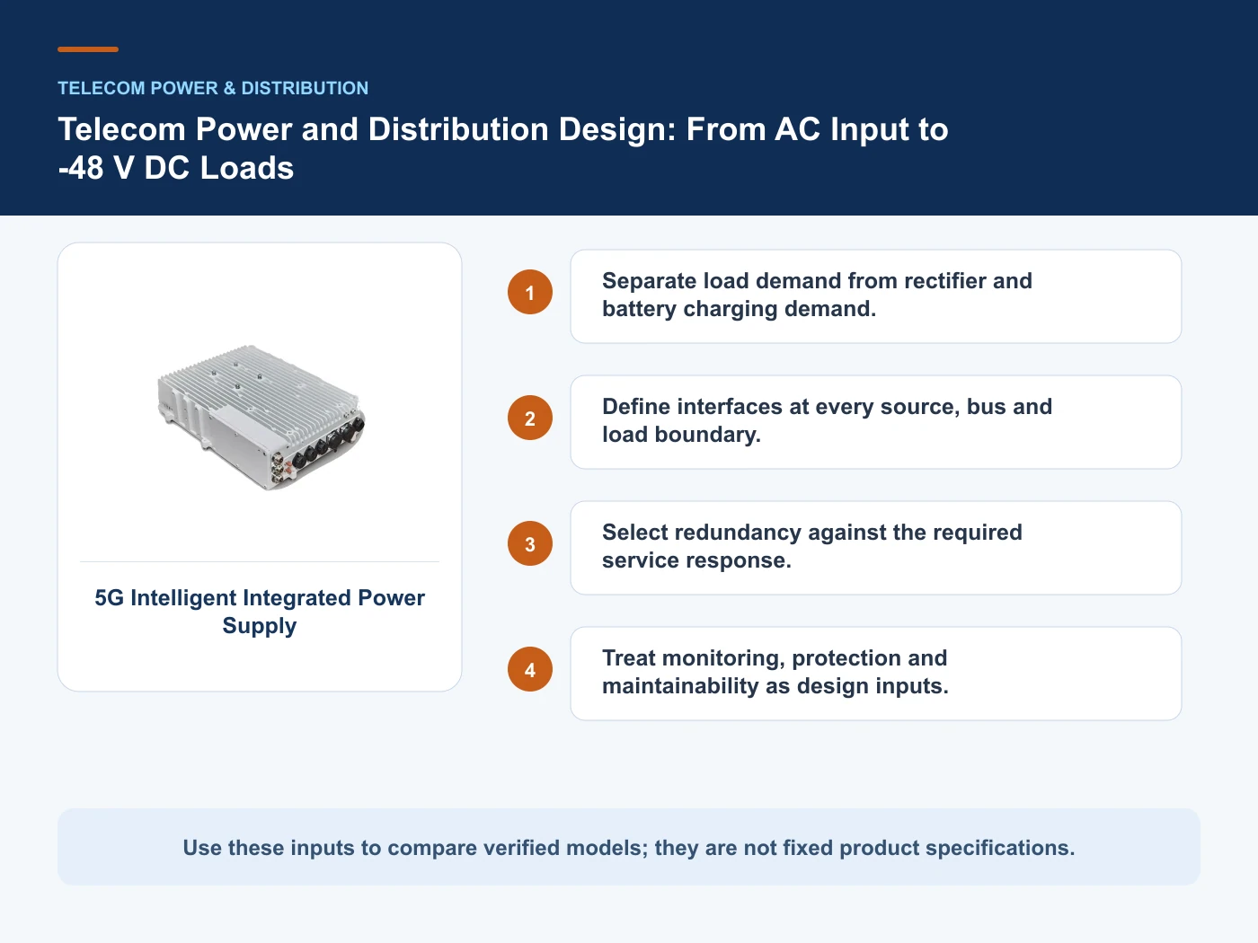
- Separate load demand from rectifier and battery charging demand.
- Define interfaces at every source, bus and load boundary.
- Select redundancy against the required service response.
- Treat monitoring, protection and maintainability as design inputs.
Separate load demand from rectifier and battery charging demand
Capture Input source and interface, then use AC input as a practical comparison point: Supply, transfer and surge/protection boundary. Before approval, verify this point: State voltage, frequency, source arrangement and fault assumptions.
Define interfaces at every source, bus and load boundary
Capture Load schedule and peak current, then use Conversion as a practical comparison point: Rectifier or UPS function. Before approval, verify this point: State output interface, module capacity and redundancy philosophy.
Select redundancy against the required service response
Capture DC voltage and branch circuits, then use Distribution as a practical comparison point: Bus and protected branch circuits. Before approval, verify this point: List steady and peak current for each load.
Treat monitoring, protection and maintainability as design inputs
Capture Rectifier/UPS redundancy, then use Backup as a practical comparison point: Battery or alternate source. Before approval, verify this point: Runtime depends on load, efficiency, temperature, ageing and operating limits.
Architecture choices and verification boundaries
This table connects AC input, DC interfaces, rectifier capacity, branch protection, redundancy and backup to the decision on telecom power system design. It is a decision aid rather than a universal performance table: exact capacity, environmental class, electrical or optical limits and certifications must come from the selected model, applicable project documents and verifiable test evidence.
| Option or input | When it fits | What must be verified |
|---|---|---|
| AC input | Supply, transfer and surge/protection boundary | State voltage, frequency, source arrangement and fault assumptions |
| Conversion | Rectifier or UPS function | State output interface, module capacity and redundancy philosophy |
| Distribution | Bus and protected branch circuits | List steady and peak current for each load |
| Backup | Battery or alternate source | Runtime depends on load, efficiency, temperature, ageing and operating limits |
Reference point: ETSI EN 300 132-2: -48 V DC input interface at telecommunications equipment and IEC 61439-2: Power switchgear and controlgear assemblies frame the terminology or method used for this telecom power system design comparison. They do not approve a product configuration; apply the edition named by the contract and local authority.
Fix the electrical boundary from source to load
Define the power path from the named AC source or transfer point through protection, conversion, DC bus, branch circuits and the terminals of each telecom load. Record source voltage and frequency, earthing arrangement, prospective fault assumptions, required DC interface range, polarity, return arrangement and every responsibility handoff. ETSI EN 300 132-2 can inform the -48 V equipment interface, while IEC 61439-2 is relevant to applicable assemblies; neither removes the need to coordinate the complete project. Battery charging, backup autonomy and alternate supplies should be shown as separate operating functions. Monitoring, surge protection, branch isolation and safe maintenance access also belong inside the system boundary when procurement responsibility is assigned.
Specify evidence for normal and abnormal operation
Acceptance evidence should connect design calculations to identifiable equipment and recorded tests. The package should include single-line diagrams, load and branch schedules, protective-device settings, cable records, controller configuration, alarm maps and approved factory-test documents. Site testing should record input and output conditions, rectifier load sharing, response to a module being removed, source-transfer behaviour where applicable, branch isolation and restoration, and communication of required alarms. Backup evidence must state the test load, temperature, battery condition, cutoff criteria and measurement method; a runtime claim without these assumptions is not reproducible. Product certificates and component reports should remain attached to their actual scope rather than being presented as proof that the integrated site has passed system-level acceptance.
Purchase capacity with its purpose clearly labelled
Issue bidders a load table that separates continuous, peak, start-up and non-critical demand. State the required recharge objective, autonomy basis and future load increments, then identify redundancy independently. An unused rectifier position may support growth, while an installed redundant module supports availability; counting the same capacity for both purposes creates a hidden shortfall. Compare quotations using the complete bill of materials, branch quantities, controller and communication interfaces, expansion limits, spare-module policy, installation scope and commissioning responsibility. Ask suppliers to identify excluded upstream protection, batteries, battery disconnects, cabling and site work. This makes the decision depend on an operable and maintainable power path rather than a headline output rating that may not match the site’s real operating states.
From requirements to an auditable project decision
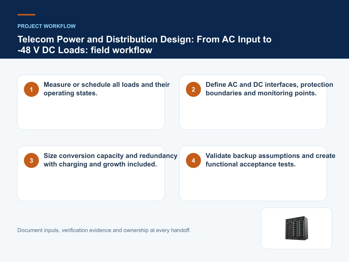
- Step 1: Measure or schedule all loads and their operating states. Record Input source and interface as an explicit input. State voltage, frequency, source arrangement and fault assumptions.
- Step 2: Define AC and DC interfaces, protection boundaries and monitoring points. Record Load schedule and peak current as an explicit input. State output interface, module capacity and redundancy philosophy.
- Step 3: Size conversion capacity and redundancy with charging and growth included. Record DC voltage and branch circuits as an explicit input. List steady and peak current for each load.
- Step 4: Validate backup assumptions and create functional acceptance tests. Record Rectifier/UPS redundancy as an explicit input. Runtime depends on load, efficiency, temperature, ageing and operating limits.
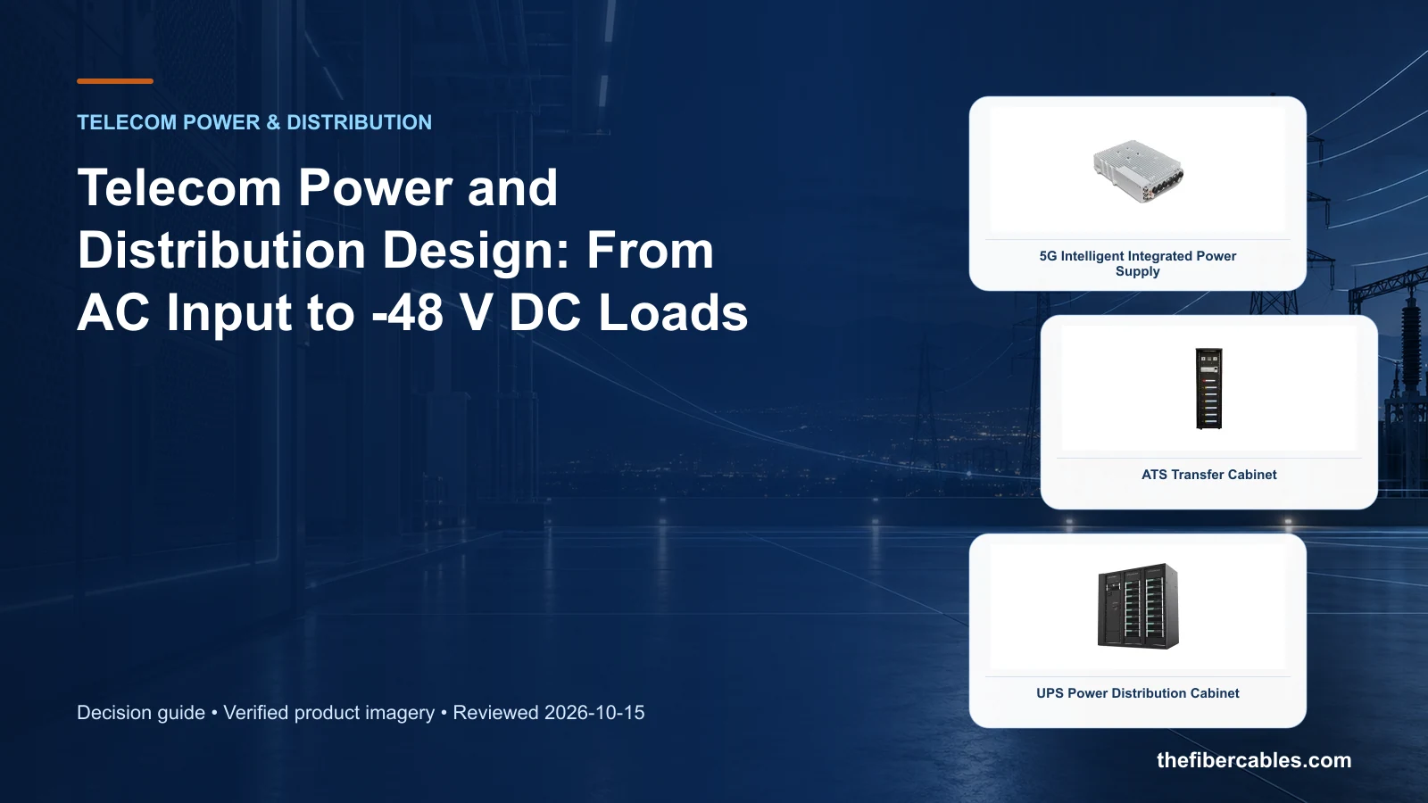
Relevant products from our communications portfolio
The products below connect the telecom power system design decision to real catalogue families and verified site photography. They are starting points, not a claim that every configuration described here is a standard stock item; confirm model, interface, rating, drawing and testing scope with the project team.
- 5G Intelligent Integrated Power Supply — use this product page as a configuration reference when you separate load demand from rectifier and battery charging demand. Confirm the offered model, interfaces, drawings and available evidence before quotation.
- Automatic Transfer Switch (ATS) Cabinet — use this product page as a configuration reference when you define interfaces at every source, bus and load boundary. Confirm the offered model, interfaces, drawings and available evidence before quotation.
- UPS Power Distribution Cabinet — use this product page as a configuration reference when you select redundancy against the required service response. Confirm the offered model, interfaces, drawings and available evidence before quotation.
For adjacent configurations, browse Telecom Power & Site Energy and compare those options against the telecom power system design inputs above, including input source and interface.
Common mistakes to avoid
- Sizing from nameplate totals without operating diversity or peak states.
- Treating a component certificate as verification of the complete assembly.
- Promising runtime without temperature, ageing and discharge assumptions.
What to include in the RFQ or design input
For telecom power system design, a complete request reduces back-and-forth and prevents a catalogue image from being mistaken for a verified configuration. Record the following fields, identify which values are mandatory or provisional and attach route, interface or layout drawings where relevant.
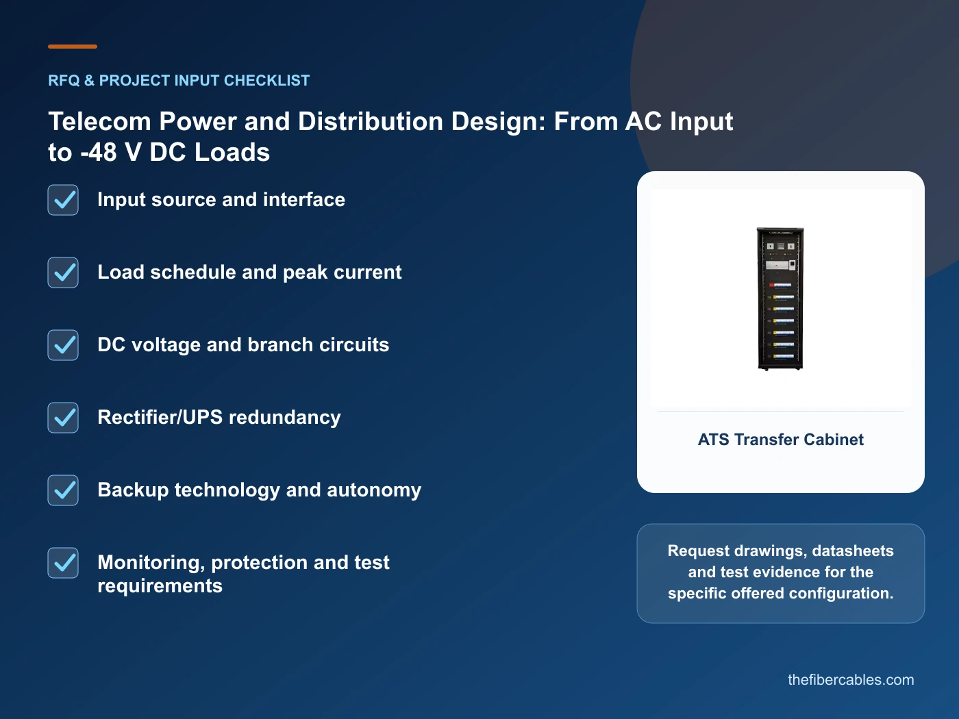
- Input source and interface
- Load schedule and peak current
- DC voltage and branch circuits
- Rectifier/UPS redundancy
- Backup technology and autonomy
- Monitoring, protection and test requirements
Questions engineers and buyers ask
What should be fixed before selecting products for telecom power system design?
Define input source and interface, load schedule and peak current, dc voltage and branch circuits first, then compare product evidence against the complete system boundary rather than one catalogue value.
How should a telecom power system design decision be documented?
Keep the route or architecture drawing, decision assumptions, selected configuration, verification evidence and acceptance records under the same revision process.
Sources and standards
For telecom power system design, the references below define relevant terminology, scope or test methods. ETSI EN 300 132-2: -48 V DC input interface at telecommunications equipment is one documented boundary for this topic; neither a standards catalogue page nor a category page proves certification of the offered product. Apply the edition adopted by the contract, destination market and authority having jurisdiction.
- ETSI EN 300 132-2: -48 V DC input interface at telecommunications equipment (V2.8.1, 10/2024). Use it to verify the terminology and scope relevant to telecom power system design; the source does not certify a specific offered product.
- IEC 61439-2: Power switchgear and controlgear assemblies (2020, Ed.3). Use it to verify the terminology and scope relevant to telecom power system design; the source does not certify a specific offered product.
- ITU-T L.1221: Evaluation and selection of stationary batteries (11/2018). Use it to verify the terminology and scope relevant to telecom power system design; the source does not certify a specific offered product.
- IEC 62619: Safety requirements for industrial secondary lithium cells and batteries (2022, Ed.2). Use it to verify the terminology and scope relevant to telecom power system design; the source does not certify a specific offered product.
Source review: Links and cited editions for telecom power system design were checked on 2026-10-15. Confirm the edition adopted by the project contract and the authority having jurisdiction.
Related guidance
AC vs DC Distribution in Telecom Sites: Architecture and Protection Boundaries • Smart Busbar vs Cable Distribution for Data-Center Rows • Embedded, Wall-Mounted or Cabinet Power System: How to Choose
Prepare a telecom power system design configuration for review
Send input source and interface, load schedule and peak current, dc voltage and branch circuits, rectifier/ups redundancy, together with quantity and delivery destination. We will help narrow the relevant product family and identify the drawings or test evidence needed for quotation.
——END——