
An 800G fiber link loss budget starts with the selected PMD, not the port speed alone. For 800GBASE-DR8, the maximum channel insertion loss is 3.0 dB over its specified 500 m single-mode application. The fiber route and every mated connector interface must be counted before selecting the MPO trunk and patching arrangement.
At 1310 nm, 500 m of OS2 fiber contributes 0.20 dB when calculated at 0.40 dB/km. Four MPO mating interfaces allocated 0.35 dB each add another 1.40 dB. The resulting 1.60 dB channel-loss estimate leaves 1.40 dB below the DR8 limit, before any separate project reserve. The connector allowance and the number of matings therefore matter at least as much as the fiber length.
Match the Loss Limit to the 800G PMD
The 800GBASE-DR8 application overview published by the TIA Fiber Optics Tech Consortium lists a 3.0 dB maximum channel insertion loss, a 1310 nm operating wavelength and a reach of up to 500 m on OS2 single-mode fiber. It summarizes an application specified under IEEE 802.3df-2024.
| Optical application | Fiber and wavelength | Maximum reach | Maximum channel insertion loss |
|---|---|---|---|
| 800GBASE-DR8 | Single-mode, 1310 nm | 500 m | 3.0 dB |
| 800GBASE-DR8-2 | Single-mode, 1310 nm | 2 km | 4.0 dB |
The 4.0 dB value belongs to the separate 800GBASE-DR8-2 application. For this DR8 route, the 800G optical loss budget must use 3.0 dB, not 4.0 dB.
The transceiver part number also determines the physical MPO interface. For example, the Cisco OSFP 800G Transceiver Modules Data Sheet identifies the OSFP-800G-DR8 with two MPO-12 APC ports and the OSFP-800G-DR8P with one MPO-16 APC port. Both are DR8 variants, but they do not use the same connector arrangement. Cisco specifies pinned module ports that mate with unpinned MPO cable plugs.
The worked route uses dual MPO-12 APC connections over OS2 fiber, without fusion splices.
Count Every MPO Mating in the Channel
A two-panel installation can use this optical path:
DR8 module A → MPO equipment jumper → Panel A → pre-terminated MPO trunk cable → Panel B → MPO equipment jumper → DR8 module B
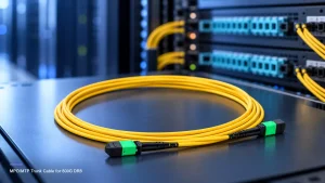
One one-way fiber path passes through four mated interfaces: one at each module port and one at each panel. The panel adapter joins two plugs into one mating. Do not add an extra adapter loss to a mated-pair loss that already includes that interface.
An 800GBASE-DR8 connection uses eight transmit and eight receive fiber lanes. Loss must be budgeted for each applicable one-way optical path; the losses of all 16 active fibers are not added together as if they formed one serial path. The end-to-end MPO polarity and Tx/Rx map must also match the optical ports. Our MPO/MTP trunk polarity and fiber-count checklist addresses this mapping decision separately.
Changing the patching architecture changes the interface count. A direct equipment-to-equipment assembly has two end matings. Adding two feed-through panels creates four. Further intermediate patching may raise the count to six or more. Each additional mating consumes part of the same PMD channel budget.
MPO Connector Insertion Loss: Low-Loss vs Standard
The MPO Series Fiber Optic Connectors offered by Huijue Group include standard-loss and low-loss single-mode options. The published APC connector-series parameters are:
| Single-mode MPO/APC option | Typical insertion loss | Maximum insertion loss | Listed return loss |
|---|---|---|---|
| Low-loss | 0.25 dB | 0.35 dB | 60 dB |
| Standard-loss | 0.35 dB | 0.50 dB | 60 dB |
These are published connector-series values. A complete channel uses actual mated interfaces, so its accepted design figures must be defined for the assembly, mating partner and measurement method being specified. Return loss is a separate optical parameter and is not added to the insertion-loss total.
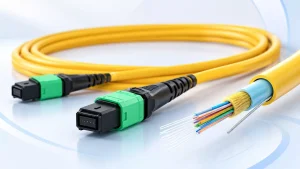
The related Pre-Terminated MPO/MTP Trunk Cable product family offers OS2 fiber, selectable MPO connector configurations, polarity options and standard- or low-loss grades. For DR8 planning, the bill of materials should identify the required two MPO-12 paths, the connector pin arrangement, the APC interface and the approved fiber map. A general product-family listing alone does not establish the maximum insertion loss of every assembled route.
The manufacturing and optical inspection overview describes connector finishing, insertion-/return-loss measurement and MPO polarity checks. Those operations relate directly to the evidence a buyer should request for a configured trunk and equipment jumper.
800GBASE-DR8 Link Loss Budget: A 500 m OS2 Example
For a 500 m route at the published OS2 attenuation reference:
Fiber loss = 0.50 km × 0.40 dB/km = 0.20 dB
With no splices, the passive channel calculation is:
Channel insertion loss = fiber loss + sum of mated-interface losses
Using 0.35 dB and 0.50 dB as design allocations per mated interface shows how the published connector-series values affect different patching layouts.
| MPO channel layout | Mated interfaces per path | Allocated loss per interface | Fiber loss | Calculated channel loss | Remaining below 3.0 dB |
|---|---|---|---|---|---|
| Direct equipment-to-equipment | 2 | 0.35 dB | 0.20 dB | 0.90 dB | 2.10 dB |
| Two feed-through panels, low-loss allocation | 4 | 0.35 dB | 0.20 dB | 1.60 dB | 1.40 dB |
| Two feed-through panels, standard-loss allocation | 4 | 0.50 dB | 0.20 dB | 2.20 dB | 0.80 dB |
| Additional patching, low-loss allocation | 6 | 0.35 dB | 0.20 dB | 2.30 dB | 0.70 dB |
Illustrative channel calculations, not factory test results. The allocated per-mating values must be matched to the specified assemblies and test reference before acceptance.
The two-panel design is especially instructive. At 0.35 dB per mating, four interfaces consume 1.40 dB; at 0.50 dB they consume 2.00 dB. Choosing the lower-loss allocation saves 0.60 dB without changing the 500 m cable route.
For the four-interface, 0.35 dB design, the budget is:
3.00 dB PMD limit − 1.40 dB interfaces − 0.20 dB fiber = 1.40 dB remaining
This remaining amount is headroom, not an additional connector rating or an installed-link measurement. Any project reserve, added splice, extra mating or stricter equipment requirement must be accommodated within it. The table does not assume a universal reserve because the required margin depends on the deployment and acceptance criteria.
Check the Reference Plane and Installed-Link Results
The optical reference planes determine which connector interfaces are included in a channel-loss calculation. A channel calculation and a field-test report can disagree if they do not cover the same endpoints. In particular, an installed-cabling test may exclude a module-side mating that the complete equipment-to-equipment channel contains. The test reference and connector boundaries therefore need to be stated alongside the result.
IEC 61280-4-2:2024 addresses attenuation and optical return-loss measurements of installed single-mode cabling. IEC 61300-3-35:2022 addresses connector end-face inspection; inspection complements, rather than replaces, optical measurement.
For an MPO DR8 installation, the handover record should include:
- Fiber and port identification: individual lane/path IDs and the end-to-end Tx/Rx map.
- Physical channel: total route length, fiber type, mated-interface locations and any splices.
- Measurement basis: wavelength, reference method, test equipment and included connector interfaces.
- Optical results: measured insertion loss for each applicable fiber path and return loss or reflectance where required.
- Acceptance decision: the applicable PMD or stricter project limit, plus a record of any failed paths and corrective work.
An average loss across the MPO assembly is insufficient when one individual fiber exceeds the limit. If a path measures high, inspect and clean the connectors, repeat the measurement using the correct reference and isolate the affected panel, jumper or trunk section. If the passive loss is acceptable but the link does not operate, verify MPO polarity and lane assignment rather than assuming that attenuation is the cause.
Specify the Trunk From the Link Budget
A purchasing request for an “800G MPO cable” does not determine the necessary interface or allowable loss. For the dual-MPO-12 DR8 arrangement, the specification should include:
| RFQ item | Required information |
|---|---|
| Optical application | 800GBASE-DR8 and the exact transceiver part number |
| MPO configuration | Two MPO-12 APC paths; compatible pinning, key orientation and polarity |
| Fiber and lengths | OS2 single-mode; trunk and equipment-jumper lengths making up the full route |
| Patching layout | Count and locations of all mated interfaces; any splices |
| Loss specification | Maximum insertion loss, measurement boundary, wavelength and connector-grade basis |
| Inspection and records | End-face criteria, loss-test records, polarity map and agreed installed-channel test procedure |
| Site requirements | Jacket type, routing constraints, labels, quantities and any environmental requirements |
An MPO-to-LC/SC/FC/ST breakout harness serves a different interface arrangement and should not be substituted for the native dual-MPO-12 link without a revised port map and loss budget.
For a trunk or jumper quotation, submit the transceiver part number, patch-panel route, total length and target maximum insertion loss through the configuration request.
——END——