
Direct answer
Use an inspect-clean-inspect workflow before mating or testing a fibre connector. Inspection identifies visible contamination or defects; cleaning removes contamination using a method compatible with the connector; re-inspection confirms the result before connection. Visual acceptance does not replace insertion-loss or return-loss testing, and a connector that remains defective after approved cleaning should be isolated for repair or replacement according to the project procedure.
Within the broader Fiber Testing & Maintenance workflow, this article focuses on fiber connector cleaning: prevent contamination-driven loss and unreliable test results. Confirm connector types and the evidence for the offered product before final engineering approval.
Inputs required before any calculation
Prevent contamination-driven loss and unreliable test results. Start with the operating requirement and installation boundary, then separate system requirements from product claims so each supplier knows which evidence must accompany the offered configuration.
- Inspect both mating endfaces where accessible.
- Use connector-specific, clean consumables and tools.
- Re-inspect after cleaning before mating.
- Separate visual result from optical-performance result.
Inspect both mating endfaces where accessible
Capture Connector types, then use Inspect as a practical comparison point: Locate debris, scratches or defects. Before approval, verify this point: Use suitable probe/tip and documented criteria.
Use connector-specific, clean consumables and tools
Capture Inspection probe tips, then use Clean as a practical comparison point: Remove contamination. Before approval, verify this point: Avoid reusing contaminated material.
Re-inspect after cleaning before mating
Capture Cleaning method, then use Re-inspect as a practical comparison point: Verify outcome. Before approval, verify this point: Repeat only within the approved procedure.
Separate visual result from optical-performance result
Capture Acceptance criteria source, then use Optical test as a practical comparison point: Verify link performance. Before approval, verify this point: Still required when specified.
A traceable sizing and verification workflow
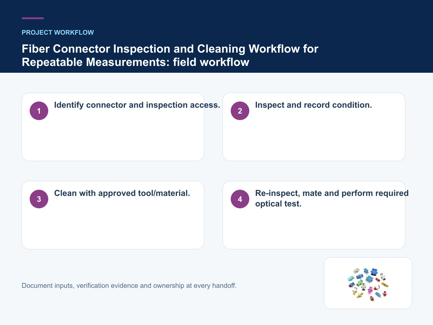
- Step 1: Identify connector and inspection access. Record Connector types as an explicit input. Use suitable probe/tip and documented criteria.
- Step 2: Inspect and record condition. Record Inspection probe tips as an explicit input. Avoid reusing contaminated material.
- Step 3: Clean with approved tool/material. Record Cleaning method as an explicit input. Repeat only within the approved procedure.
- Step 4: Re-inspect, mate and perform required optical test. Record Acceptance criteria source as an explicit input. Still required when specified.
Calculation boundaries and acceptance limits
This table connects inspection, optical-loss measurement, OTDR analysis, acceptance records and maintenance workflow to the decision on fiber connector cleaning. It is a decision aid rather than a universal performance table: exact capacity, environmental class, electrical or optical limits and certifications must come from the selected model, applicable project documents and verifiable test evidence.
| Option or input | When it fits | What must be verified |
|---|---|---|
| Inspect | Locate debris, scratches or defects | Use suitable probe/tip and documented criteria |
| Clean | Remove contamination | Avoid reusing contaminated material |
| Re-inspect | Verify outcome | Repeat only within the approved procedure |
| Optical test | Verify link performance | Still required when specified |
Reference point: IEC 61300-3-35: Visual inspection of fibre optic connector endfaces and FOA: Fiber optic testing frame the terminology or method used for this fiber connector cleaning comparison. They do not approve a product configuration; apply the edition named by the contract and local authority.
Relevant products from our communications portfolio
The products below connect the fiber connector cleaning decision to real catalogue families and verified site photography. They are starting points, not a claim that every configuration described here is a standard stock item; confirm model, interface, rating, drawing and testing scope with the project team.
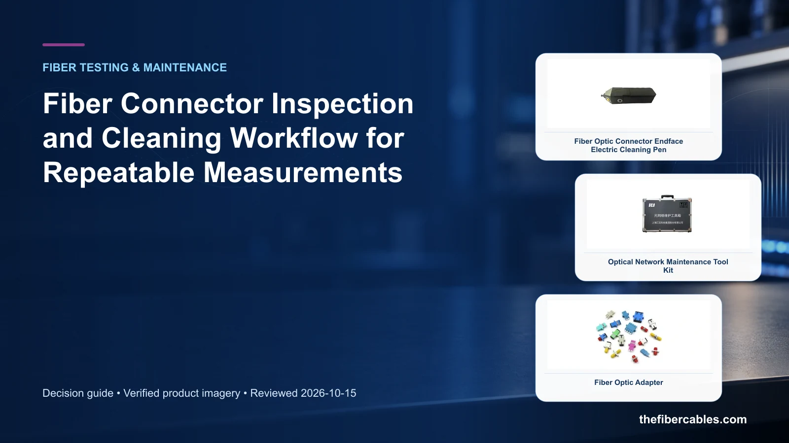
- Powered Fiber Optic Connector End-Face Cleaner — use this product page as a configuration reference when you inspect both mating endfaces where accessible. Confirm the offered model, interfaces, drawings and available evidence before quotation.
- Optical Network Maintenance Tool Kit — use this product page as a configuration reference when you use connector-specific, clean consumables and tools. Confirm the offered model, interfaces, drawings and available evidence before quotation.
- Fiber Optic Adapter — use this product page as a configuration reference when you re-inspect after cleaning before mating. Confirm the offered model, interfaces, drawings and available evidence before quotation.
For adjacent configurations, browse Fiber Splicing, Cleaning & Test Tools and compare those options against the fiber connector cleaning inputs above, including connector types.
What to include in the RFQ or design input
For fiber connector cleaning, a complete request reduces back-and-forth and prevents a catalogue image from being mistaken for a verified configuration. Record the following fields, identify which values are mandatory or provisional and attach route, interface or layout drawings where relevant.
- Connector types
- Inspection probe tips
- Cleaning method
- Acceptance criteria source
- Record requirement
- Optical test method
Common mistakes to avoid
- Mating a connector without inspecting it.
- Touching or reusing cleaning surfaces.
- Treating a visual pass as proof of link loss.
Questions engineers and buyers ask
Can fiber connector cleaning be sized from a nominal rating alone?
No. The calculation must include connector types, inspection probe tips, cleaning method plus applicable margins, derating and acceptance limits.
Which result should appear in the RFQ?
State the design inputs, calculation method, selected value, reserve or margin and evidence required from the offered configuration.
Sources and standards
For fiber connector cleaning, the references below define relevant terminology, scope or test methods. IEC 61300-3-35: Visual inspection of fibre optic connector endfaces is one documented boundary for this topic; neither a standards catalogue page nor a category page proves certification of the offered product. Apply the edition adopted by the contract, destination market and authority having jurisdiction.
- IEC 61300-3-35: Visual inspection of fibre optic connector endfaces (2022, Ed.3). Use it to verify the terminology and scope relevant to fiber connector cleaning; the source does not certify a specific offered product.
- FOA: Fiber optic testing (Technical reference accessed 2026-10-15). Use it to verify the terminology and scope relevant to fiber connector cleaning; the source does not certify a specific offered product.
Source review: Links and cited editions for fiber connector cleaning were checked on 2026-10-15. Confirm the edition adopted by the project contract and the authority having jurisdiction.
Related guidance
Fiber Testing and Acceptance Guide: OTDR, Optical Power, Loss and Connector Quality • FTTH and ODN Acceptance Testing Workflow Before Service Activation • OTDR vs Optical Power Meter and Light Source: Which Test Answers Which Question?
Prepare a fiber connector cleaning configuration for review
Send connector types, inspection probe tips, cleaning method, acceptance criteria source, together with quantity and delivery destination. We will help narrow the relevant product family and identify the drawings or test evidence needed for quotation.
——END——