
Direct answer
An OTDR and a light-source/power-meter set are complementary. The source and meter measure end-to-end insertion loss using a stated reference method. The OTDR estimates distance and event behavior from backscatter and reflection, helping locate connectors, splices, bends and breaks. Because the measurement principles differ, an OTDR trace should not automatically replace the end-to-end loss test required by an acceptance plan.
Within the broader Fiber Testing & Maintenance workflow, this article focuses on OTDR vs optical power meter: choose test instruments by measurement objective. Confirm link type and length and the evidence for the offered product before final engineering approval.
Decisions that separate the options
Choose test instruments by measurement objective. Start with the operating requirement and installation boundary, then separate system requirements from product claims so each supplier knows which evidence must accompany the offered configuration.
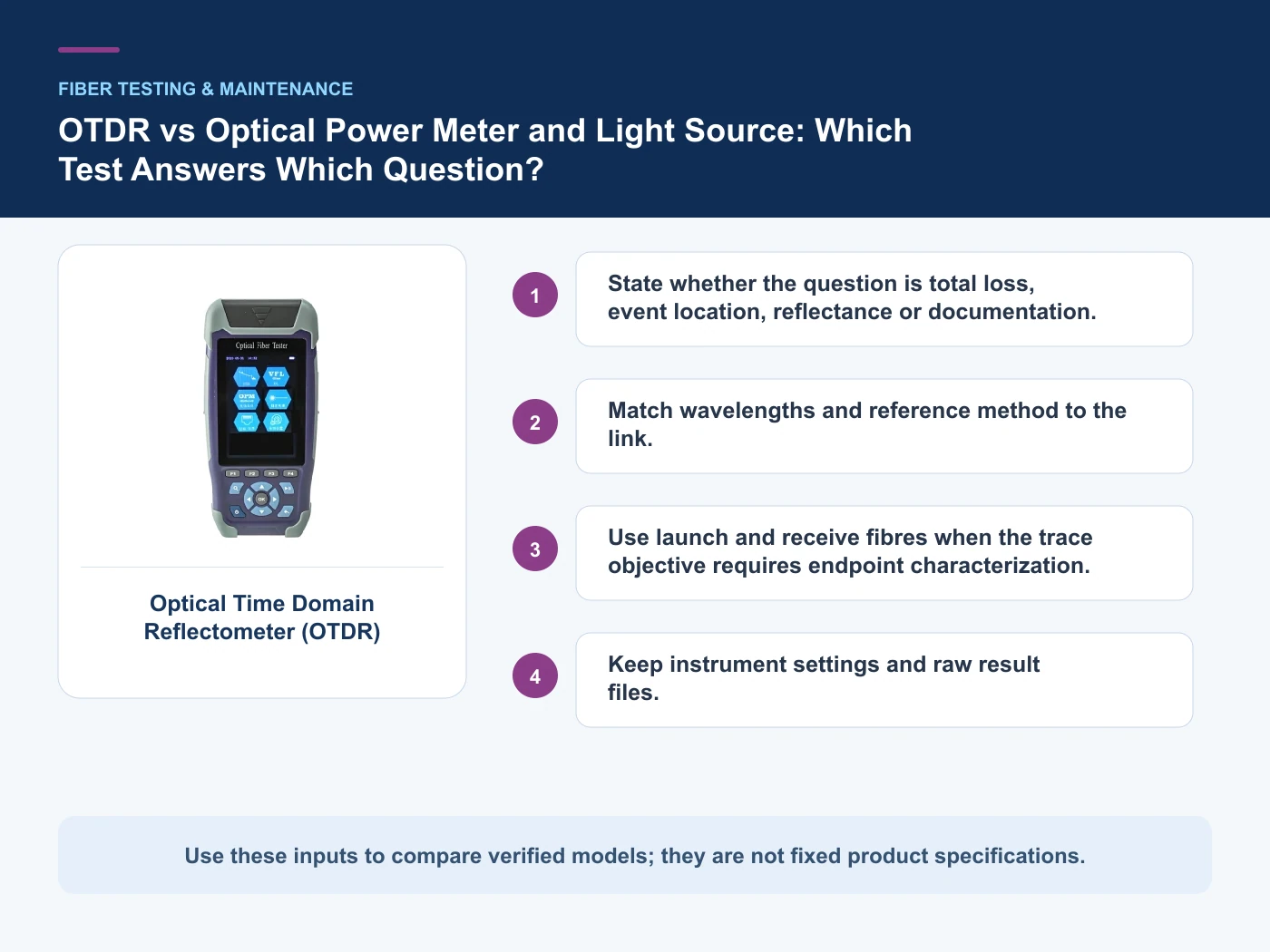
- State whether the question is total loss, event location, reflectance or documentation.
- Match wavelengths and reference method to the link.
- Use launch and receive fibres when the trace objective requires endpoint characterization.
- Keep instrument settings and raw result files.
State whether the question is total loss, event location, reflectance or documentation
Capture Link type and length, then use Source + power meter / OLTS as a practical comparison point: End-to-end insertion loss. Before approval, verify this point: Requires reference procedure and stable test cords.
Match wavelengths and reference method to the link
Capture Wavelengths, then use OTDR as a practical comparison point: Length and event trace. Before approval, verify this point: Settings influence resolution, range and dead zones.
Use launch and receive fibres when the trace objective requires endpoint characterization
Capture Reference method, then use Inspection scope as a practical comparison point: Connector condition. Before approval, verify this point: Perform before mating; it does not measure optical loss.
Keep instrument settings and raw result files
Capture Required OTDR directions, then use Source + power meter / OLTS as a practical comparison point: End-to-end insertion loss. Before approval, verify this point: Requires reference procedure and stable test cords.
Where the options diverge
This table connects inspection, optical-loss measurement, OTDR analysis, acceptance records and maintenance workflow to the decision on OTDR vs optical power meter. It is a decision aid rather than a universal performance table: exact capacity, environmental class, electrical or optical limits and certifications must come from the selected model, applicable project documents and verifiable test evidence.
| Option or input | When it fits | What must be verified |
|---|---|---|
| Source + power meter / OLTS | End-to-end insertion loss | Requires reference procedure and stable test cords |
| OTDR | Length and event trace | Settings influence resolution, range and dead zones |
| Inspection scope | Connector condition | Perform before mating; it does not measure optical loss |
Reference point: ITU-T G.650.3: Test methods for installed single-mode fibre cable links and IEC 61280-4-2: Installed single-mode cabling attenuation and optical return loss frame the terminology or method used for this OTDR vs optical power meter comparison. They do not approve a product configuration; apply the edition named by the contract and local authority.
Relevant products from our communications portfolio
The products below connect the OTDR vs optical power meter decision to real catalogue families and verified site photography. They are starting points, not a claim that every configuration described here is a standard stock item; confirm model, interface, rating, drawing and testing scope with the project team.
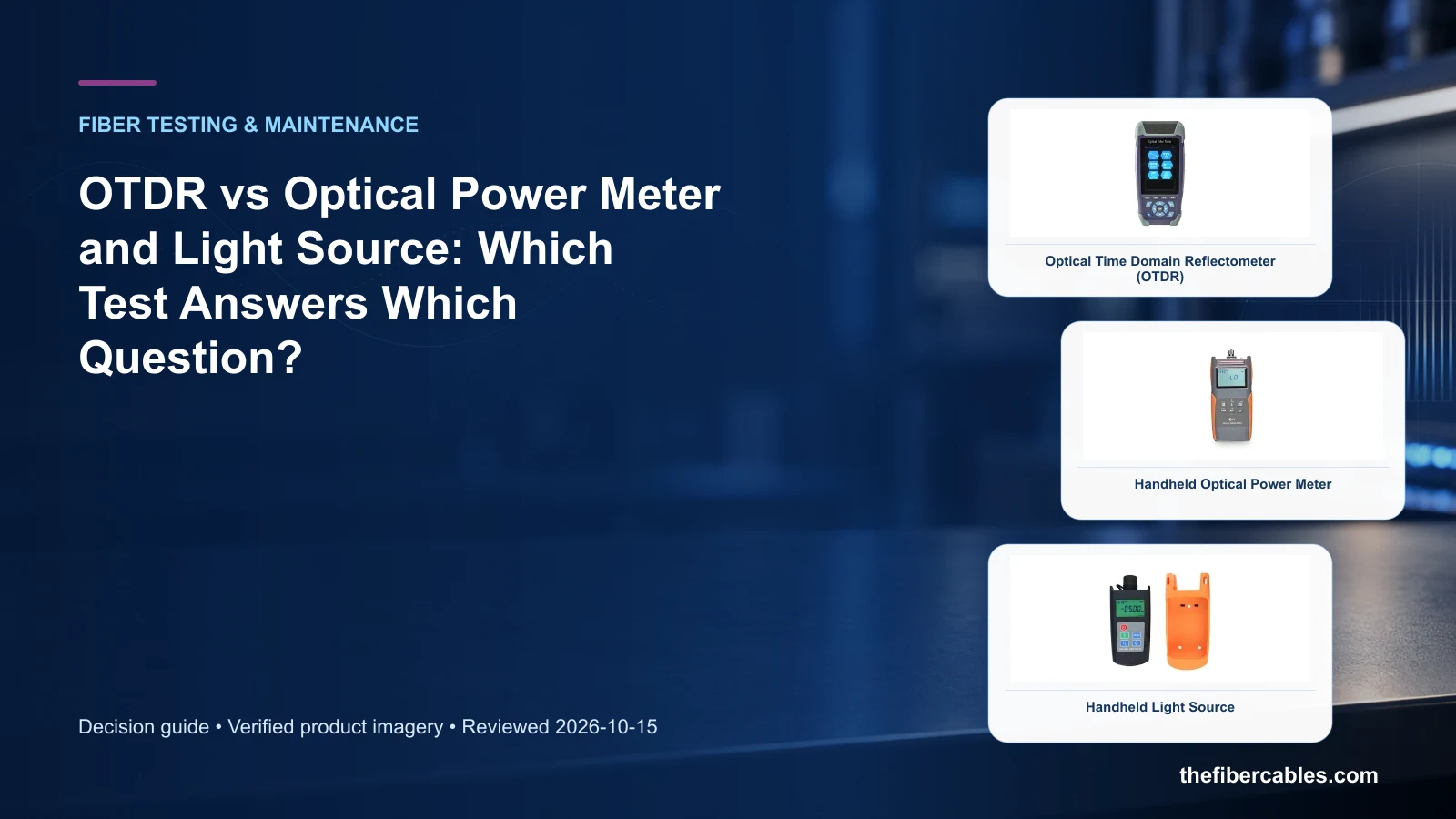
- Optical Time Domain Reflectometer (OTDR) — use this product page as a configuration reference when you state whether the question is total loss, event location, reflectance or documentation. Confirm the offered model, interfaces, drawings and available evidence before quotation.
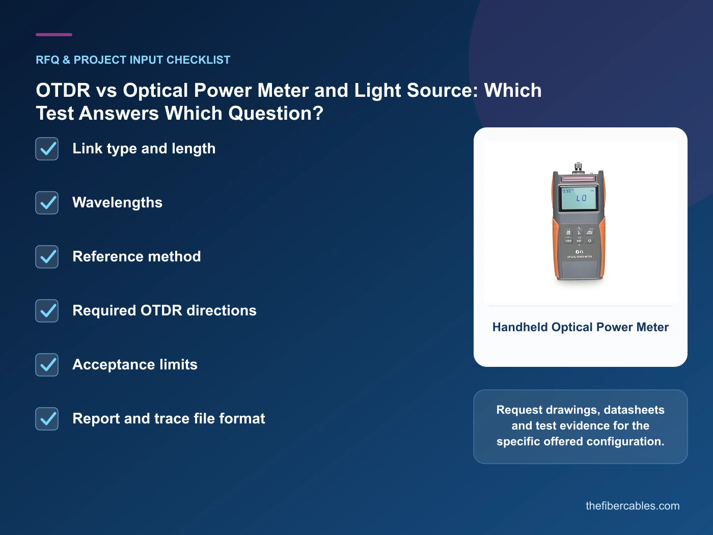
- Handheld Optical Power Meter — use this product page as a configuration reference when you match wavelengths and reference method to the link. Confirm the offered model, interfaces, drawings and available evidence before quotation.
- Handheld Optical Light Source — use this product page as a configuration reference when you use launch and receive fibres when the trace objective requires endpoint characterization. Confirm the offered model, interfaces, drawings and available evidence before quotation.
For adjacent configurations, browse Fiber Splicing, Cleaning & Test Tools and compare those options against the OTDR vs optical power meter inputs above, including link type and length.
A comparison workflow that avoids label-based selection
- Step 1: Write the test objective and contractual limit. Record Link type and length as an explicit input. Requires reference procedure and stable test cords.
- Step 2: Prepare and inspect reference/test cords. Record Wavelengths as an explicit input. Settings influence resolution, range and dead zones.
- Step 3: Run the end-to-end loss test. Record Reference method as an explicit input. Perform before mating; it does not measure optical loss.
- Step 4: Add OTDR analysis where route or event evidence is required. Record Required OTDR directions as an explicit input. Requires reference procedure and stable test cords.
Common mistakes to avoid
- Using an OTDR’s total trace estimate as the contractual insertion-loss result without agreement.
- Testing dirty connectors repeatedly.
- Comparing traces taken with different index, pulse or wavelength settings.
What to include in the RFQ or design input
For OTDR vs optical power meter, a complete request reduces back-and-forth and prevents a catalogue image from being mistaken for a verified configuration. Record the following fields, identify which values are mandatory or provisional and attach route, interface or layout drawings where relevant.
- Link type and length
- Wavelengths
- Reference method
- Required OTDR directions
- Acceptance limits
- Report and trace file format
Questions engineers and buyers ask
Which option is better for OTDR vs optical power meter?
There is no universal winner. Choose the option that satisfies state whether the question is total loss, event location, reflectance or documentation. and match wavelengths and reference method to the link., then verify the offered model and project conditions.
Can price alone decide this comparison?
No. Compare installed interfaces, protection, testing, maintenance and expansion obligations as well as unit price.
Sources and standards
For OTDR vs optical power meter, the references below define relevant terminology, scope or test methods. ITU-T G.650.3: Test methods for installed single-mode fibre cable links is one documented boundary for this topic; neither a standards catalogue page nor a category page proves certification of the offered product. Apply the edition adopted by the contract, destination market and authority having jurisdiction.
- ITU-T G.650.3: Test methods for installed single-mode fibre cable links (08/2017). Use it to verify the terminology and scope relevant to OTDR vs optical power meter; the source does not certify a specific offered product.
- IEC 61280-4-2: Installed single-mode cabling attenuation and optical return loss (2024, Ed.3). Use it to verify the terminology and scope relevant to OTDR vs optical power meter; the source does not certify a specific offered product.
- FOA: Optical Time Domain Reflectometer (Technical reference accessed 2026-10-15). Use it to verify the terminology and scope relevant to OTDR vs optical power meter; the source does not certify a specific offered product.
Source review: Links and cited editions for OTDR vs optical power meter were checked on 2026-10-15. Confirm the edition adopted by the project contract and the authority having jurisdiction.
Related guidance
Fiber Testing and Acceptance Guide: OTDR, Optical Power, Loss and Connector Quality • How Launch and Receive Fibers Change OTDR Measurements • Insertion Loss vs Return Loss: What Each Reveals About a Fiber Link
Prepare a OTDR vs optical power meter configuration for review
Send link type and length, wavelengths, reference method, required otdr directions, together with quantity and delivery destination. We will help narrow the relevant product family and identify the drawings or test evidence needed for quotation.
——END——