
Direct answer
Outdoor telecom cabinet thermal design begins with a heat and moisture balance, not a cooling-product name. List the dissipation and operating limits of installed equipment, define ambient temperature and humidity, account for solar exposure and wall construction, and state the target internal conditions. Then decide whether the cabinet can use natural or filtered ventilation, a closed-loop heat exchanger, active air conditioning, heating or a coordinated combination. Airflow must reach the equipment without short-circuiting, while doors, compartments, filters and cable zones remain serviceable. Condensation risk requires review during changing weather and low-load periods as well as peak heat. The final design should document inputs, calculation assumptions, selected devices, alarm points, installation clearances and a verification method for the configured cabinet.
This pillar guide connects heat load, solar gain, condensation, airflow, heat exchangers, active cooling and battery thermal boundaries. Use it to define project inputs before narrowing to a product family.
Scope boundary: This is the system-level heat-and-moisture design boundary. Use the cooling-method comparison for architecture trade-offs and the air-conditioner sizing guide when active refrigeration has already been selected.
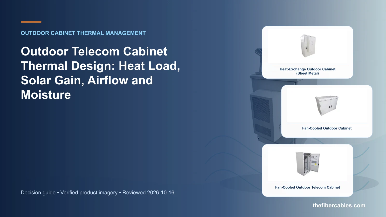
System boundaries to define before product selection
Build a cabinet thermal boundary from equipment loss, climate, solar exposure, construction and allowable internal conditions. Start with the operating requirement and installation boundary, then separate system requirements from product claims so each supplier knows which evidence must accompany the offered configuration.
- Calculate heat and moisture boundaries before selecting thermal hardware.
- Use equipment operating limits rather than a convenient room-temperature target.
- Coordinate airflow with rack layout, compartments and service access.
- Define monitoring and verification for the final integrated cabinet.
Calculate heat and moisture boundaries before selecting thermal hardware
Capture Equipment heat dissipation by operating mode, then use Heat input as a practical comparison point: Equipment loss and solar gain. Before approval, verify this point: Use documented operating cases.
Use equipment operating limits rather than a convenient room-temperature target
Capture Ambient temperature and humidity profile, then use Heat path as a practical comparison point: Walls, airflow and thermal device. Before approval, verify this point: Model the configured enclosure.
Coordinate airflow with rack layout, compartments and service access
Capture Solar exposure and cabinet orientation, then use Acceptance as a practical comparison point: Temperatures, alarms and verification. Before approval, verify this point: Agree limits and test conditions.
Define monitoring and verification for the final integrated cabinet
Capture Target internal temperature and humidity, then use Heat input as a practical comparison point: Equipment loss and solar gain. Before approval, verify this point: Use documented operating cases.
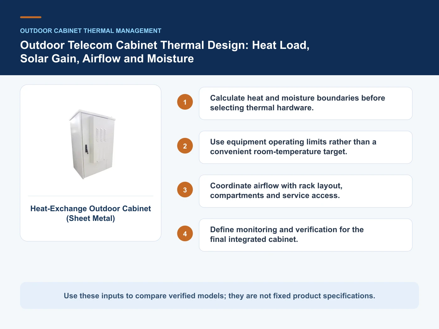
Architecture choices and verification boundaries
This table connects heat load, solar gain, condensation, airflow, heat exchangers, active cooling and battery thermal boundaries to the decision on outdoor telecom cabinet thermal design. It is a decision aid rather than a universal performance table: exact capacity, environmental class, electrical or optical limits and certifications must come from the selected model, applicable project documents and verifiable test evidence.
| Option or input | When it fits | What must be verified |
|---|---|---|
| Heat input | Equipment loss and solar gain | Use documented operating cases |
| Heat path | Walls, airflow and thermal device | Model the configured enclosure |
| Acceptance | Temperatures, alarms and verification | Agree limits and test conditions |
Reference point: ETSI TR 102 489: Thermal management guidance for telecommunications equipment and ETSI EN 300 019-1-4: Environmental conditions and environmental tests for telecommunications equipment — stationary use at non-weatherprotected locations frame the terminology or method used for this outdoor telecom cabinet thermal design comparison. They do not approve a product configuration; apply the edition named by the contract and local authority.
Build one traceable heat-and-moisture boundary
Record equipment dissipation by operating state, external ambient conditions, solar exposure, wall construction and the acceptable internal range. Keep measured values, supplier data and engineering assumptions distinguishable so later changes can be recalculated.
Include low-load and shutdown periods in the moisture review. Condensation risk can emerge when equipment is not producing peak heat, especially during rapid weather changes or cold starts.
Select the thermal method after the boundary is known
Ventilation, heat exchange and active refrigeration impose different contaminant, sealing, power and maintenance boundaries. Compare them against the required internal condition and local service model rather than selecting from a cooling-product name.
Map supply and return paths around real equipment. Short-circuit airflow, blocked filters, closed cable zones and unplanned partitions can invalidate a nominal cooling selection.
Verify the configured cabinet
The approved package should identify calculation inputs, selected devices, setpoints, alarms, sensor positions, external clearances and condensate handling. FAT can check assembly and controls; site acceptance must also check installation conditions and actual airflow paths.
Keep the thermal calculation under revision control with the equipment list. Added radios, batteries or power modules should trigger an impact review before they are installed.
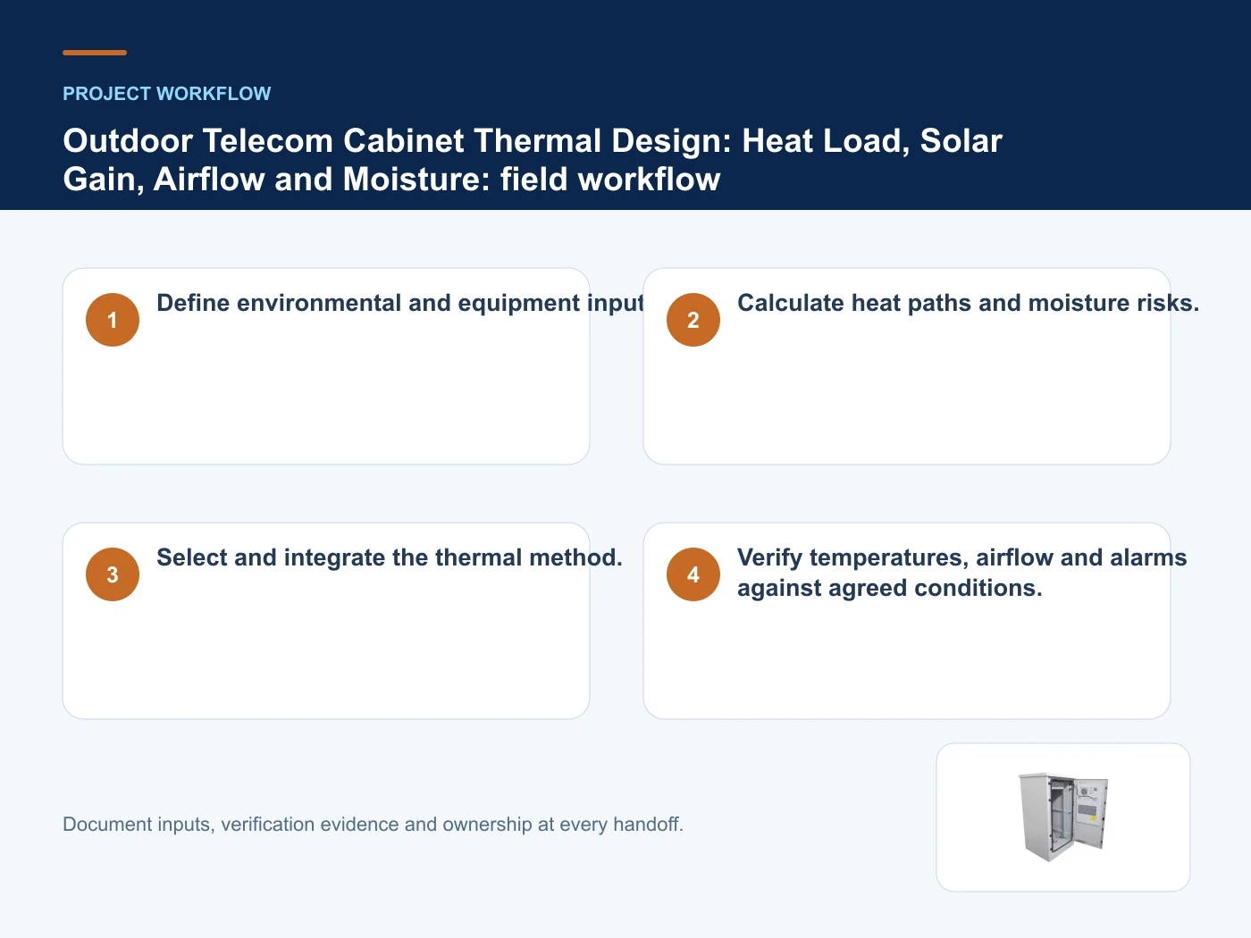
From requirements to an auditable project decision
- Step 1: Define environmental and equipment inputs. Record Equipment heat dissipation by operating mode as an explicit input. Use documented operating cases.
- Step 2: Calculate heat paths and moisture risks. Record Ambient temperature and humidity profile as an explicit input. Model the configured enclosure.
- Step 3: Select and integrate the thermal method. Record Solar exposure and cabinet orientation as an explicit input. Agree limits and test conditions.
- Step 4: Verify temperatures, airflow and alarms against agreed conditions. Record Target internal temperature and humidity as an explicit input. Use documented operating cases.
Relevant products from our communications portfolio
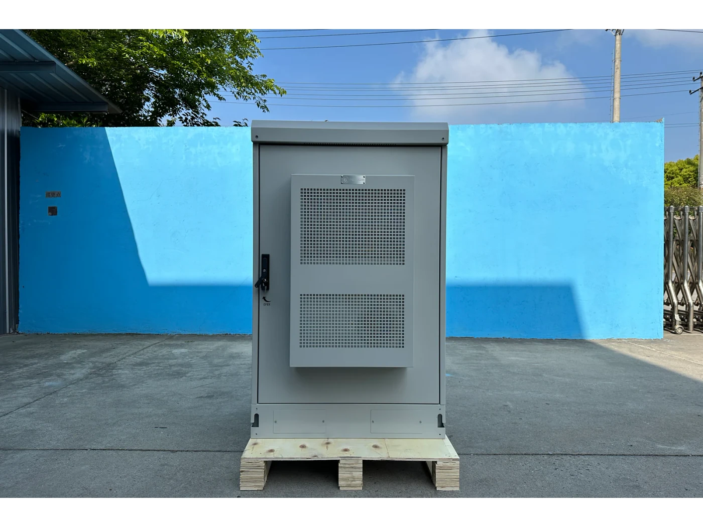
The products below connect the outdoor telecom cabinet thermal design decision to real catalogue families and verified site photography. They are starting points, not a claim that every configuration described here is a standard stock item; confirm model, interface, rating, drawing and testing scope with the project team.
- Heat-Exchanger-Cooled Outdoor Telecom Cabinet (HJ-XDF-JF41) — use this product page as a configuration reference when you calculate heat and moisture boundaries before selecting thermal hardware. Confirm the offered model, interfaces, drawings and available evidence before quotation.
- Fan-Cooled Outdoor Cabinet — use this product page as a configuration reference when you use equipment operating limits rather than a convenient room-temperature target. Confirm the offered model, interfaces, drawings and available evidence before quotation.
- Fan-Cooled Outdoor Telecom Cabinet — use this product page as a configuration reference when you coordinate airflow with rack layout, compartments and service access. Confirm the offered model, interfaces, drawings and available evidence before quotation.
- Air-Conditioned Outdoor Cabinet (Sheet Metal) — use this product page as a configuration reference when you define monitoring and verification for the final integrated cabinet. Confirm the offered model, interfaces, drawings and available evidence before quotation.
For adjacent configurations, browse Outdoor Cabinets & Site Infrastructure and compare those options against the outdoor telecom cabinet thermal design inputs above, including equipment heat dissipation by operating mode.
Common mistakes to avoid
- Selecting an air conditioner from cabinet volume alone.
- Ignoring solar gain or low-load condensation.
- Testing an empty cabinet instead of the configured airflow path.
What to include in the RFQ or design input
For outdoor telecom cabinet thermal design, a complete request reduces back-and-forth and prevents a catalogue image from being mistaken for a verified configuration. Record the following fields, identify which values are mandatory or provisional and attach route, interface or layout drawings where relevant.
- Equipment heat dissipation by operating mode
- Ambient temperature and humidity profile
- Solar exposure and cabinet orientation
- Target internal temperature and humidity
- Cabinet material and wall construction
- Airflow and compartment layout
- Cooling, heating and alarm interfaces
- Required thermal verification
Questions engineers and buyers ask
How should heat input be evaluated for outdoor telecom cabinet thermal design?
Use equipment loss and solar gain as the operating context, record equipment heat dissipation by operating mode, and verify use documented operating cases for the exact offered configuration.
Which project input can change the outdoor telecom cabinet thermal design decision?
Calculate heat and moisture boundaries before selecting thermal hardware. Recheck that decision when ambient temperature and humidity profile or solar exposure and cabinet orientation changes.
Sources and standards
The references below define terminology, scope or test methods relevant to outdoor telecom cabinet thermal design. They do not certify an offered product; confirm the edition adopted by the contract and destination authority.
- ETSI TR 102 489: Thermal management guidance for telecommunications equipment (V1.3.1, 06/2013). Use it to verify the terminology and scope relevant to outdoor telecom cabinet thermal design; the source does not certify a specific offered product.
- ETSI EN 300 019-1-4: Environmental conditions and environmental tests for telecommunications equipment — stationary use at non-weatherprotected locations (V3.1.1, 2026). Use it to verify the terminology and scope relevant to outdoor telecom cabinet thermal design; the source does not certify a specific offered product.
- IEC 60721-3-4: Classification of environmental conditions — stationary use at non-weatherprotected locations (2019, Ed. 3). Use it to verify the terminology and scope relevant to outdoor telecom cabinet thermal design; the source does not certify a specific offered product.
- IEC 62208:2023 — Empty enclosures for low-voltage switchgear and controlgear assemblies (2023, Ed. 3). Use it to verify the terminology and scope relevant to outdoor telecom cabinet thermal design; the source does not certify a specific offered product.
Source review: Links and cited editions for outdoor telecom cabinet thermal design were checked on 2026-10-16. Confirm the edition adopted by the project contract and the authority having jurisdiction.
Related guidance
Fan Cooling vs Heat Exchanger vs Air Conditioner • Cabinet and Equipment-Room Air Conditioner Sizing • Preventing Condensation in Outdoor Telecom Cabinets: Dew Point, Air Exchange and Heaters
Prepare a outdoor telecom cabinet thermal design configuration for review
Send equipment heat dissipation by operating mode, ambient temperature and humidity profile, solar exposure and cabinet orientation, target internal temperature and humidity, quantity and delivery destination. Huijue Group can review the configuration boundary and identify the drawings or evidence needed for a factory quotation.
——END——