
Passive optical distribution
Match splitter or WDM architecture to wavelength plan, ratio, package and insertion-loss targets.
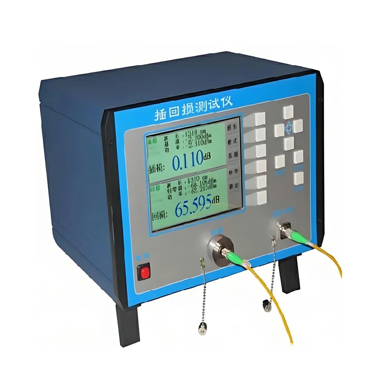
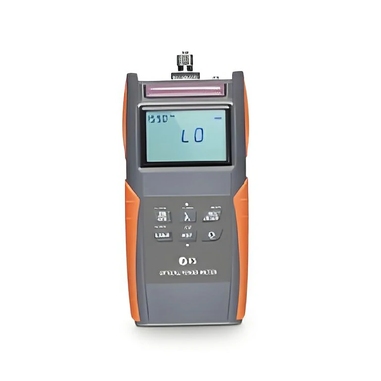
The IR550 benchtop tester measures insertion loss at 850/1300/1310/1550 nm and return loss at 1310/1550 nm for fiber assemblies.
The IR550 is a bench instrument for manual insertion-loss and return-loss measurement of patch cords, pigtails and assembled optical links. It combines the source and measurement functions needed to check how much signal is lost through an assembly and how much light is reflected back toward the source.
The listed insertion-loss wavelengths are 850, 1300, 1310 and 1550 nm; return-loss testing is listed at 1310 and 1550 nm. Supported interfaces include FC, SC and ST plus universal 2.5 mm and 1.25 mm options, making the fixture and reference-cord schedule an important part of the configuration.
Define connector families, polish types, fiber type, test wavelengths, reference method and pass/fail criteria before selecting fixtures. The documented operating range is -10°C to 45°C and storage/transport range is -25°C to 70°C. Production use may also require an agreed calibration and verification schedule.
Huijue Group can review a private-label bench package with reference cords, mating adapters and fixture organization based on customer samples or an approved interface drawing. Measurement sequence, calibration scope, software or data-record needs, quantity and final acceptance procedure require engineering confirmation.
| Serial No. | Performance Item | IR550 Benchtop Insertion & Return Loss Tester |
| 1 | Test Wavelengths | Insertion Loss: 850/1300/1310/1550nm; Return Loss: 1310/1550nm |
| 2 | Test Accuracy | Insertion Loss: ≤±0.25dB; Return Loss: ≤±0.5dB |
| 3 | Interfaces | FC/SC/ST/Universal 2.5mm/Universal 1.25mm |
| 4 | Measurement Range | Insertion Loss: -62dBm~+6dBm; Return Loss: 0~85dB |
Use stable reference leads, inspect and clean every interface, and allow the tester to reach a stable bench temperature. Return-loss results are particularly sensitive to connector condition and the reference arrangement.
Buyer Questions
Answers specific to Benchtop Insertion/Return Loss Tester selection, configuration and purchasing.
Both universal 1.25 mm and 2.5 mm interfaces are listed, subject to the correct fixture and reference arrangement.
Not in every case. The listed insertion-loss set includes 850/1300/1310/1550 nm, while return loss is listed at 1310/1550 nm.
Yes, a sample or interface drawing can be reviewed, but the final fixture, method and acceptance limits must be approved before production.
Use the deployment context to narrow the configuration before comparing dimensions, capacities and options.
Match splitter or WDM architecture to wavelength plan, ratio, package and insertion-loss targets.
Coordinate connector, polish, fiber grade, polarity and cable length across patching points.
Plan MPO/MTP trunks and harnesses around port mapping, breakout format and rack density.
Select splicing, cleaning and test tools for the connector types and measurements used on site.
Before quotation: confirm capacity, interfaces, installation environment, power conditions, quantity and required options.