
Passive optical distribution
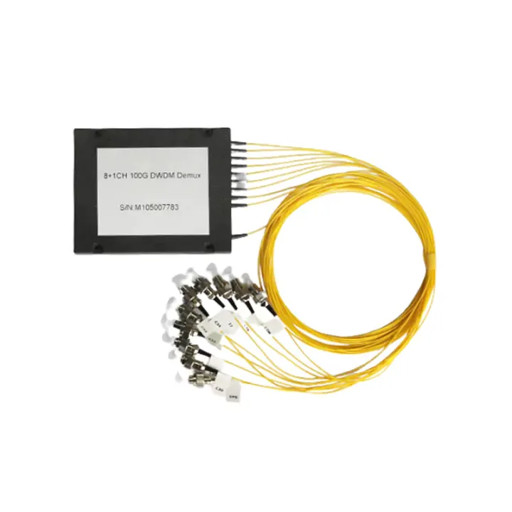
Match splitter or WDM architecture to wavelength plan, ratio, package and insertion-loss targets.
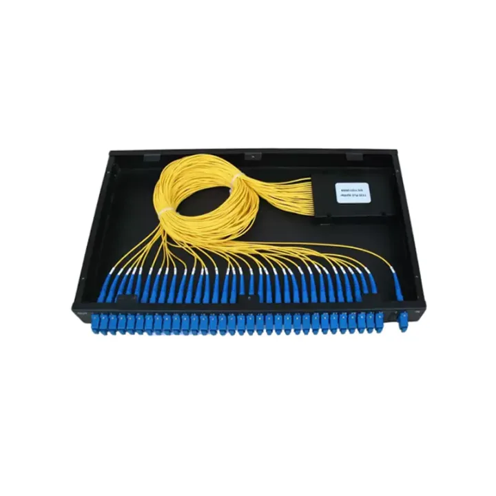
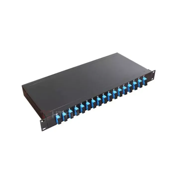
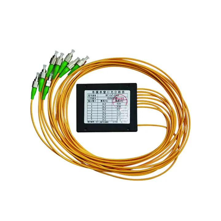
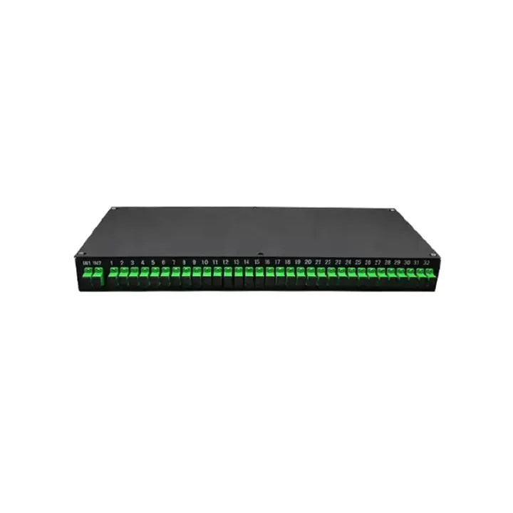
A cassette-style PLC splitter for protected installation in standard or custom enclosures, with compact 1×N and 2×N optical distribution.
Box-Type Optical Splitter Series packages a PLC splitter in a compact cassette that can be installed in standard or project-specific optical enclosures. The box protects the splitting element and organizes the input and output leads while allowing the host cabinet or terminal box to provide final mounting and access.
The listed range spans 1×4 to 1×64 and 2×4 to 2×64 over 1260–1650 nm. Cassette dimensions increase with port count, so enclosure space and lead routing should be checked against the selected ratio.
Confirm split ratio, input count, cassette mounting space, fiber lead diameter and length, connector/polish and cable-exit direction. Check the complete optical budget and ensure the host enclosure has enough protected slack storage.
Huijue Group can review OEM cassette splitters, drawing-based lead exits, port labels and private-label packaging. A host-box sample can support fit checks. Dimensions, material, loss grade, connectors, test scope and volume require final approval.
| Parameters | 1×4 | 1×8 | 1×16 | 1×32 | 1×64 | ||
| 1 | Operating Bandwidth (nm) | 1260 - 1650 | |||||
| 2 | Insertion Loss (dB) | Maximum | 7.4 | 10.5 | 13.8 | 17.1 | 20.4 |
| 3 | Polarization Dependent Loss (PDL) (dB) | Maximum | 0.2 | 0.2 | 0.3 | 0.3 | 0.3 |
| 4 | Return Loss (RL) (dB) | Minimum | 45 (PC); 50 (UPC); 55 (APC) | ||||
| 5 | Splitting Uniformity (dB) | Maximum | 0.7 | 0.8 | 1.0 | 1.5 | 2.0 |
| 6 | Directivity (dB) | Minimum | 55 | 55 | 55 | 55 | 55 |
Notes: 1. Applicable to devices with all integrated components;
2. All parameters are tested including connectors, under the condition of λ=1310/1550nm;
3. The test wavelengths for splitting uniformity are 1310nm, 1490nm, and 1550nm. For the wavelength ranges of 1260nm-1300nm and 1600nm-1650nm, the splitting uniformity index is increased by 0.5dB on the basis of the above indicators.
| Parameters | 2×4 | 2×8 | 2×16 | 2×32 | 2×64 | ||
| 1 | Operating Bandwidth (nm) | 1260 - 1650 | |||||
| 2 | Insertion Loss (dB) | Maximum | 7.7 | 10.8 | 14.1 | 17.4 | 20.6 |
| 3 | Polarization Dependent Loss (PDL) (dB) | Maximum | 0.2 | 0.2 | 0.3 | 0.3 | 0.3 |
| 4 | Return Loss (RL) (dB) | Minimum | 45 (PC); 50 (UPC); 55 (APC) | ||||
| 5 | Splitting Uniformity (dB) | Maximum | 0.7 | 0.8 | 1.0 | 1.5 | 2.0 |
| 6 | Directivity (dB) | Minimum | 55 | 55 | 55 | 55 | 55 |
Notes: 1. Applicable to uniform devices;
2. All parameters are tested including connectors, under the condition of λ=1310/1550nm;
3. The test wavelengths for splitting uniformity are 1310nm, 1490nm, and 1550nm. For the wavelength ranges of 1260nm-1300nm and 1600nm-1650nm, the splitting uniformity index is increased by 0.5dB on the basis of the above indicators.
The cassette needs a compatible host enclosure for outdoor or harsh-site service. Protect all leads from sharp bends and tension, and cap unused connector interfaces.
Buyer Questions
Answers specific to Box-Type Optical Splitter Series selection, configuration and purchasing.
It can be reviewed from a drawing or sample, but mounting space, lead exits and bend radius must be approved.
No specific outdoor enclosure rating is stated. The complete host box or cabinet provides site protection.
Use the deployment context to narrow the configuration before comparing dimensions, capacities and options.
Match splitter or WDM architecture to wavelength plan, ratio, package and insertion-loss targets.
Coordinate connector, polish, fiber grade, polarity and cable length across patching points.
Plan MPO/MTP trunks and harnesses around port mapping, breakout format and rack density.
Select splicing, cleaning and test tools for the connector types and measurements used on site.
Before quotation: confirm capacity, interfaces, installation environment, power conditions, quantity and required options.