
Passive optical distribution
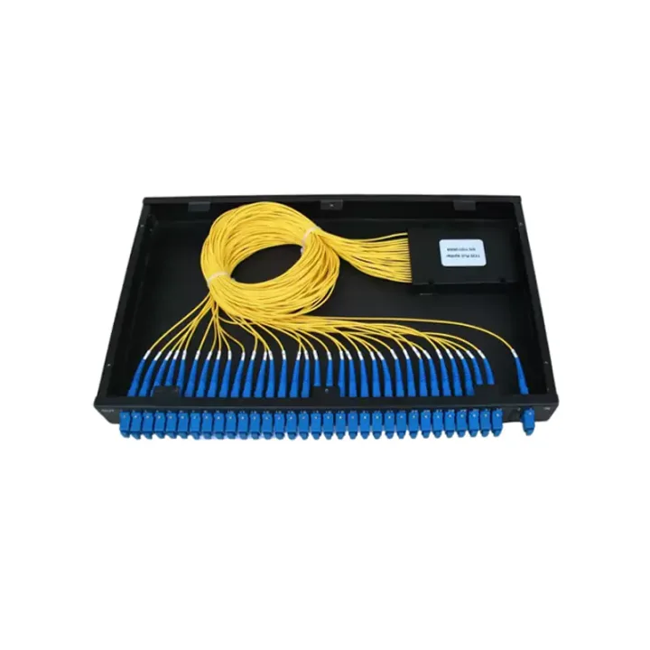
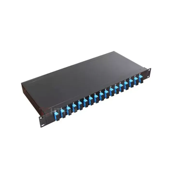
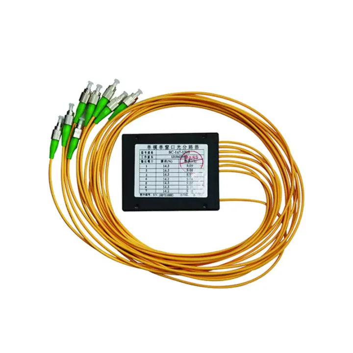
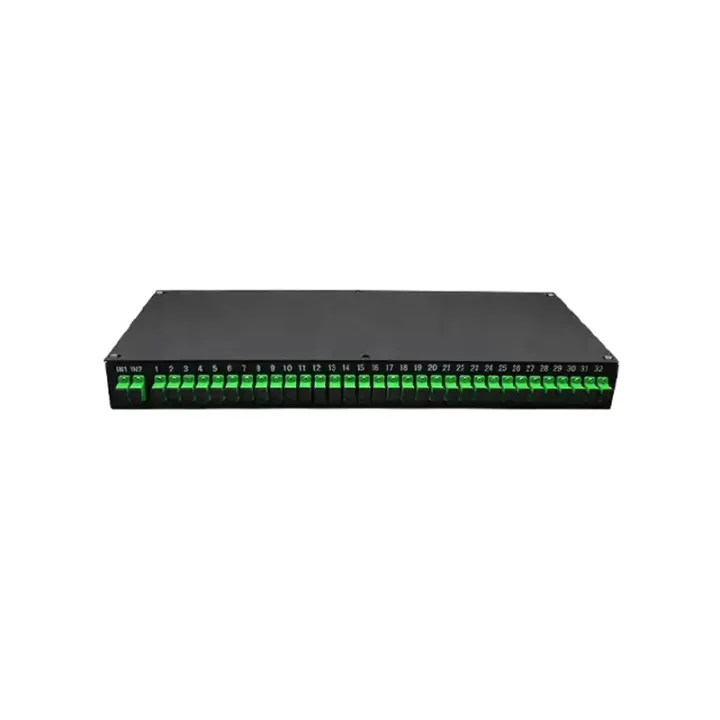
Match splitter or WDM architecture to wavelength plan, ratio, package and insertion-loss targets.
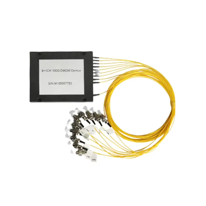
A 100 or 200 GHz DWDM multiplexer/demultiplexer for combining or separating C/L-band optical channels on one fiber.
Dense Wavelength Division Multiplexer (DWDM) Series combines several closely spaced optical wavelengths onto one fiber or separates them at the receiving end. The current component uses multi-cavity dielectric thin-film filtering and supports 100 or 200 GHz channel spacing in the C and L bands.
The series can be configured for two, four, eight or sixteen channels in the published loss table. A DWDM order must identify the exact ITU channel plan, direction and port map; channel count alone does not define the component.
Provide the complete channel list, 100 or 200 GHz spacing, mux or demux direction, common/express/monitor port needs, connector/polish, fiber leads and package. Check per-channel insertion loss and isolation in the system optical budget.
Huijue Group can review OEM/private-label DWDM modules and drawing-based port layouts. Customer channel plans or equipment samples can guide connector and package choices; filter set, port map, optical tests, lead length, quantity and tooling remain subject to engineering confirmation.
| Parameter | Specification | Unit | |
| ITU Grid (C and L Band) | nm | ||
| Channel Bandwidth | λc + 0.11/0.125 (minimum) | λc + 0.25 (minimum) | nm |
| Channel Spacing | 100 | 200 | GHz |
| Channel Flatness | ≤ 0.4 | ≤ 0.4 | nm |
| Insertion Loss | ≤ 1.6 (2 Channel) | ≤ 1.6 (2 Channel) | dB |
| ≤ 2.4 (4 Channel) | ≤ 2.4 (4 Channel) | dB | |
| ≤ 2.5 (8 Channel) | ≤ 3.2 (16 Channel) | dB | |
| ≤ 3.5 (16 Channel) | ≤ 3.5 (16 Channel) | dB | |
| Adjacent Channel Isolation | ≥ 30 | dB | |
| Non-Adjacent Channel Isolation | ≥ 45 | dB | |
| Insertion Loss Temperature Coefficient | ≤ 0.005 | dB/℃ | |
| Polarization Dependent Loss (PDL) | ≤ 0.1 | dB | |
| Polarization Mode Dispersion (PMD) | ≤ 0.1 | ps | |
| Return Loss (RL) | ≥ 45 | dB | |
| Directivity | ≥ 55 | dB | |
| Operating Temperature | 0 to 70 | ℃ | |
| Storage Temperature | -40 to 85 | ℃ | |
| Package Dimensions | 80 (L) x 58 (W) x 6.6 (H) | mm | |
The published operating range is 0°C to 70°C and storage range is -40°C to 85°C. Install the module in a protected enclosure with controlled fiber strain and bend radius.
Buyer Questions
Answers specific to Dense Wavelength Division Multiplexer (DWDM) Series selection, configuration and purchasing.
They define different separations between adjacent DWDM channels. The transceivers and network channel plan must use the same grid.
Passive WDM components are often reciprocal, but the ordered port map and labeling must still identify the intended installation direction.
Yes. The exact ITU wavelengths, port functions and channel count are core manufacturing inputs.
Use the deployment context to narrow the configuration before comparing dimensions, capacities and options.
Match splitter or WDM architecture to wavelength plan, ratio, package and insertion-loss targets.
Coordinate connector, polish, fiber grade, polarity and cable length across patching points.
Plan MPO/MTP trunks and harnesses around port mapping, breakout format and rack density.
Select splicing, cleaning and test tools for the connector types and measurements used on site.
Before quotation: confirm capacity, interfaces, installation environment, power conditions, quantity and required options.