
Passive optical distribution
Match splitter or WDM architecture to wavelength plan, ratio, package and insertion-loss targets.
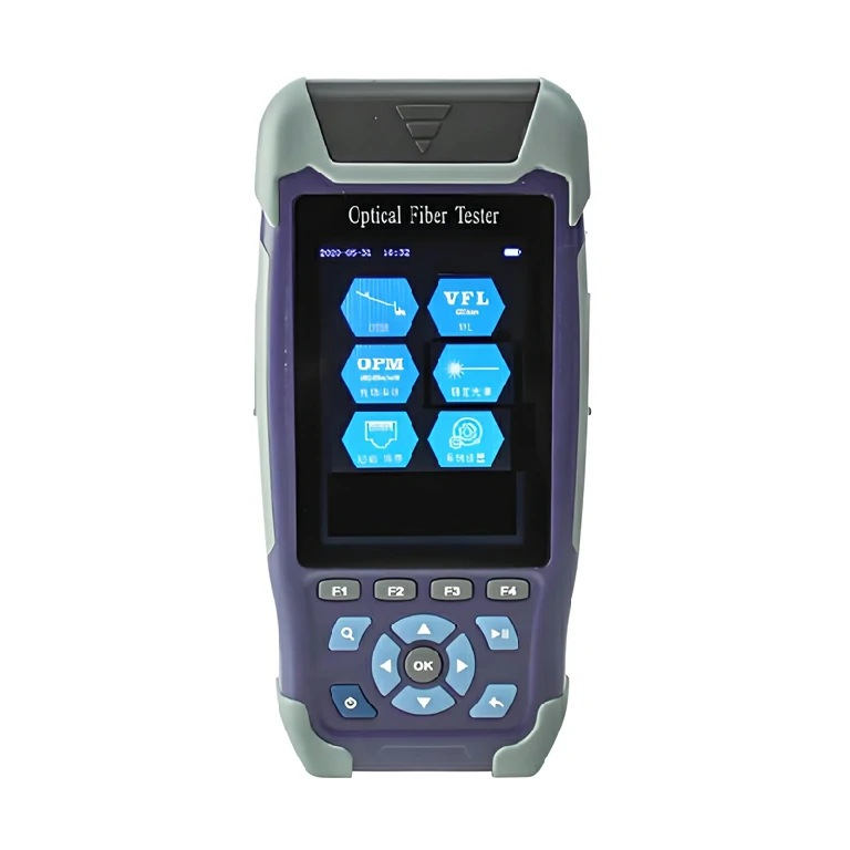
A 1310/1550 nm optical time domain reflectometer for locating fiber events and evaluating distance and attenuation, with a listed display range extending to 260 km.
The Optical Time Domain Reflectometer launches a test pulse into a fiber and analyzes returned light to show distance, attenuation and reflective events along the route. It is used to locate breaks, identify splice or connector events and understand how loss is distributed rather than producing only one end-to-end power value.
The listed unit operates at 1310 and 1550 nm ±20 nm, with a 0.1 to 260 km display range, 0.001 dB attenuation resolution and 4 cm sampling resolution. Actual measurable reach and event visibility depend on link loss, pulse settings, reflectance and test setup. Display range describes the distance scale and does not establish the instrument’s optical dynamic range.
Provide the fiber type, route length, expected link loss, shortest spacing between events and required report format. Launch and receive fibers may be needed to evaluate near-end and far-end connectors. Confirm the required connector adapter and any power-meter or VFL functions separately rather than assuming they are included.
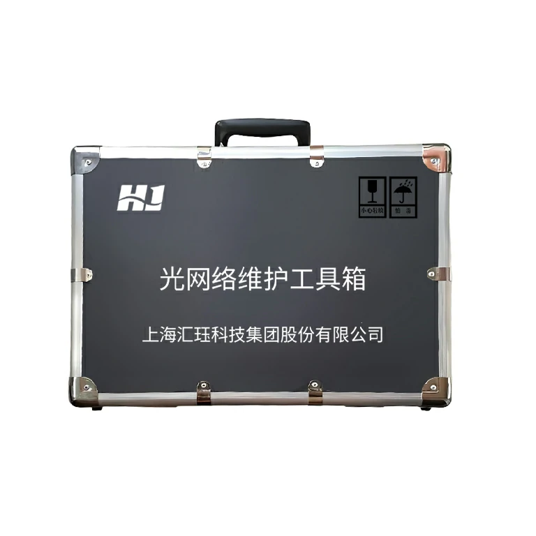
Huijue Group can review an OEM OTDR package with selected adapters, launch leads, case organization and private-label artwork. Connector samples or interface drawings can guide accessory checks. Engineering must confirm instrument configuration, any fixture tooling, calibration evidence, reporting functions and acceptance tests before quantity and delivery scope are agreed.
| Serial No. | Performance Item | SmartOTDR Series Optical Time Domain Reflectometer |
| 1 | Center Wavelength | 1310/1550 nm±20 nm |
| 2 | Attenuation Resolution | 0.001 dB |
| 3 | Sampling Resolution | 4 cm |
| 4 | Event Blind Zone | 1.35 m |
| 5 | Attenuation Blind Zone | 4.5 m |
| 6 | Distance Accuracy | (±1m)±Sampling Resolution±(1×10⁻⁵×Distance) (Excluding uncertainty caused by group refractive index) |
| 7 | Display Range | 0.1 km ~ 260 km |
The stated storage and transport range is -20°C to 60°C. Keep the test port and launch cable clean, enter the correct group refractive index, and choose pulse width and range for the specific route. Never connect an OTDR to a live link unless the test procedure permits it.
Buyer Questions
Answers specific to Optical Time Domain Reflectometer (OTDR) selection, configuration and purchasing.
No. It describes the distance scale. Practical reach depends on route attenuation, event reflectance, pulse settings and the instrument configuration.
Comparing traces at the two listed wavelengths can help characterize a single-mode link and identify wavelength-dependent loss behavior.
No. An OTDR provides distributed event information; end-to-end insertion-loss acceptance commonly uses a stabilized source and power meter as a separate method.
Use the deployment context to narrow the configuration before comparing dimensions, capacities and options.
Match splitter or WDM architecture to wavelength plan, ratio, package and insertion-loss targets.
Coordinate connector, polish, fiber grade, polarity and cable length across patching points.
Plan MPO/MTP trunks and harnesses around port mapping, breakout format and rack density.
Select splicing, cleaning and test tools for the connector types and measurements used on site.
Before quotation: confirm capacity, interfaces, installation environment, power conditions, quantity and required options.