
Fiber Access & ODN Solutions
FTTx & ODN Network Deployment
Plan the feeder, distribution and subscriber side of an FTTx network as one serviceable optical path, with cable, closures, splitters, cabinets, terminal boxes and pre-terminated connectivity selected from verified project inputs.

Planning and configuration
Solution overview
An FTTx network is easier to install and maintain when the optical path is planned as one system instead of a list of unrelated parts. This solution covers the route from an exchange, central office or equipment room through feeder and distribution sections to the final subscriber connection. Huijue Group can coordinate fiber-optic cable, optical distribution frames, splice closures, street or building distribution points, PLC splitters, adapters, pigtails, patch cords and drop-cable termination around the topology supplied by the project team.
The objective is not to impose one fixed bill of materials. A high-rise building, low-density rural route, campus and multi-dwelling development place different demands on split ratios, closure capacity, cable construction, connector format and installation access. The configuration therefore begins with the network drawing, subscriber count and route conditions.
Define the optical path before choosing products
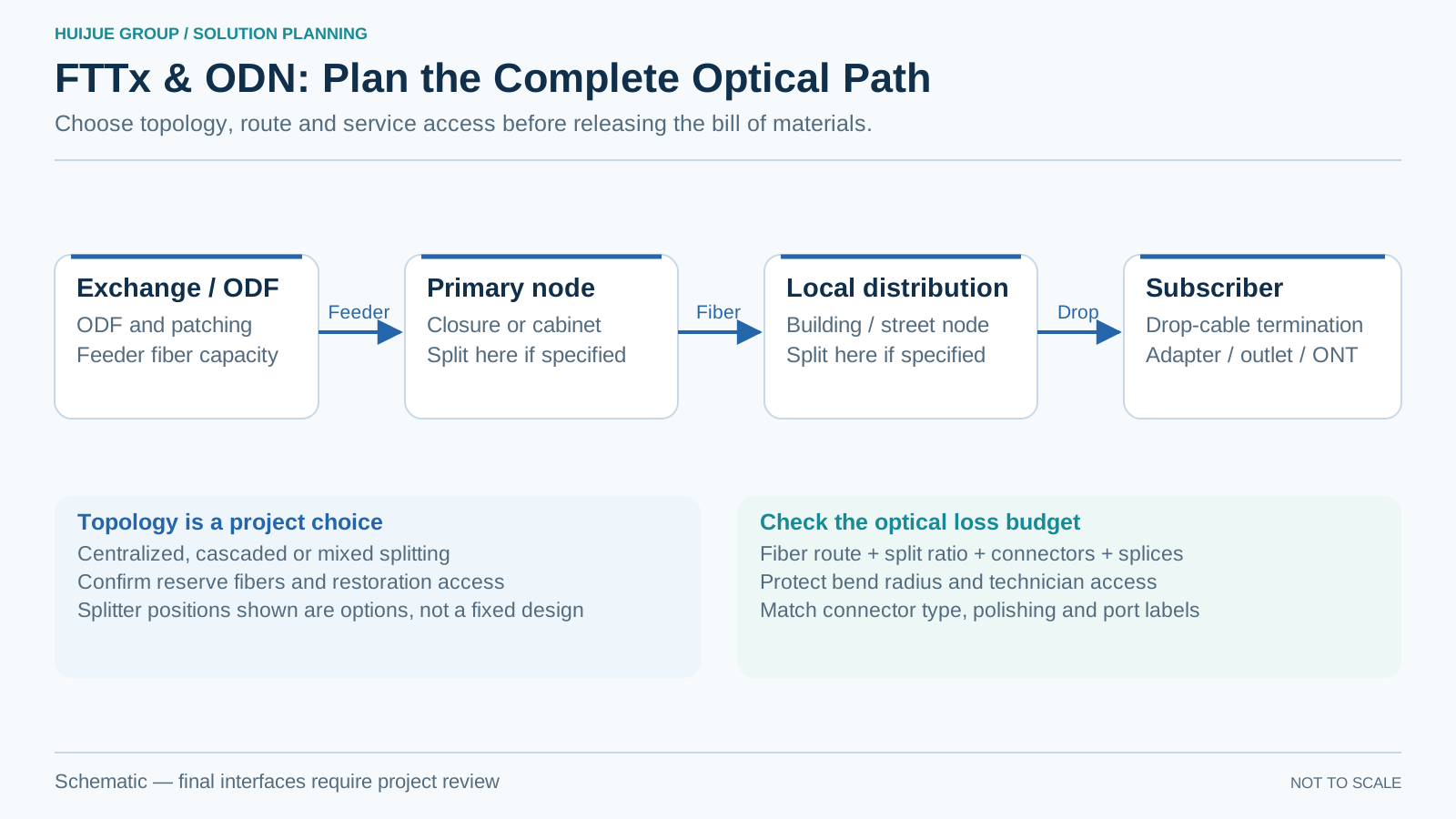
The first design step is to divide the network into functional zones. The feeder segment carries capacity from the active network location to a primary distribution point. The distribution segment branches that capacity toward buildings, streets or service areas. The drop segment completes the connection to the subscriber outlet or optical network terminal. Establishing those boundaries makes fiber counts, reserve capacity and splice responsibilities visible before hardware is ordered.
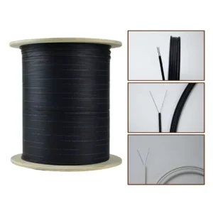
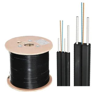
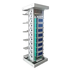
Central-office fibers can be organized in an optical main distribution frame or smaller ODF units. Field branching may use closures, cross-connect cabinets or splitter boxes according to access, mounting and environmental exposure. On the subscriber side, bend performance, support method and indoor fire requirements guide the choice between products such as bend-insensitive FTTH drop cable and a self-supporting drop cable.
Configuration areas
| Design area | What the project must define |
|---|---|
| Cable route | Confirm duct, direct-buried, aerial, façade, riser and indoor sections separately; one cable construction is rarely appropriate for every section. |
| Fiber plan | Document working fibers, growth allowance, spare fibers and restoration capacity at each branching point. |
| Splitting | Establish centralized, cascaded or mixed splitting, including split ratio, connectorized or spliced input/output and insertion-loss budget. |
| Termination | Match adapter type, polishing format, pigtail jacket and panel density across frames, cabinets and terminal boxes. |
| Service access | Protect bend radius, leave controlled slack and keep labels readable without disturbing adjacent circuits. |
Equipment matched to the deployment stage
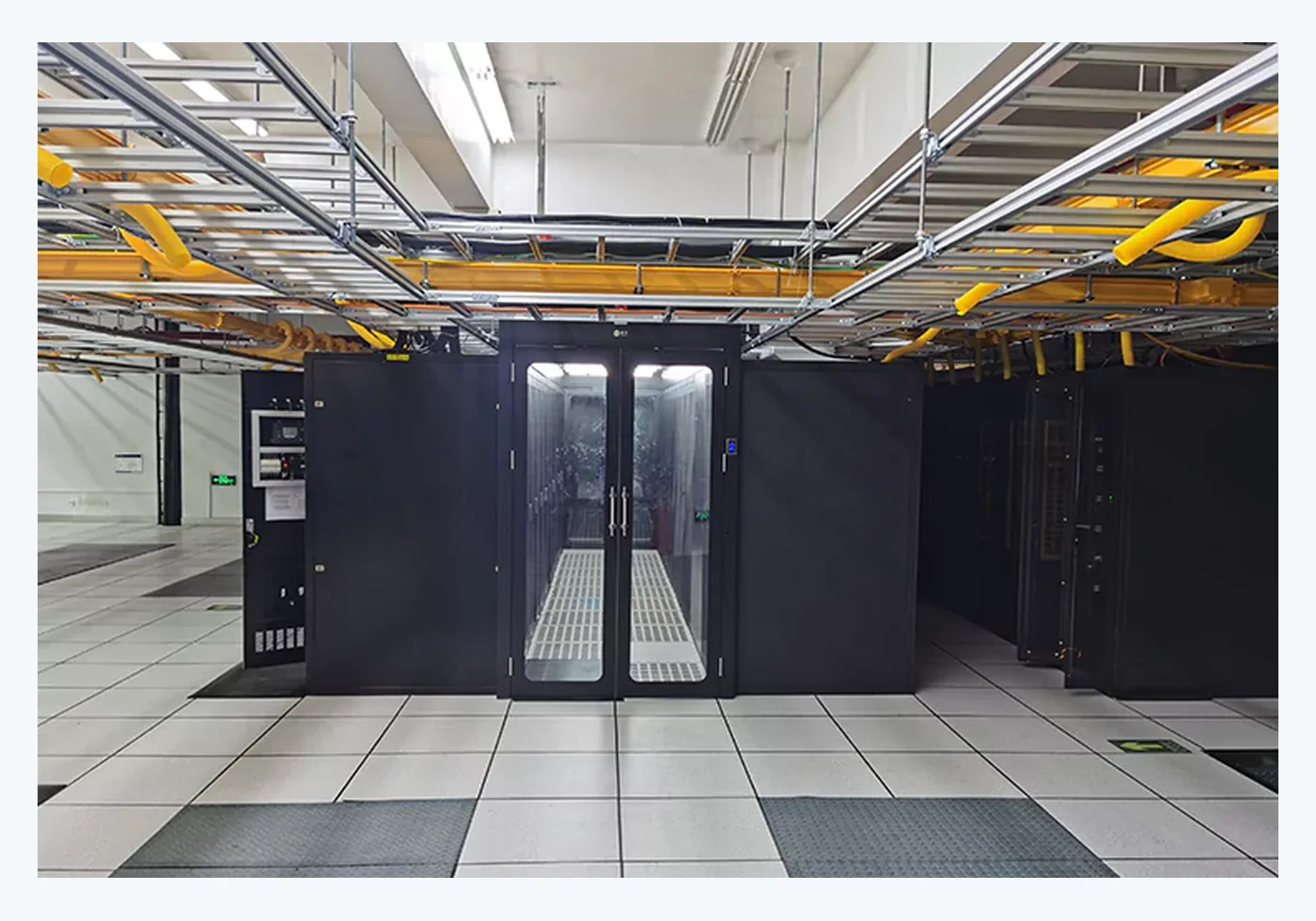
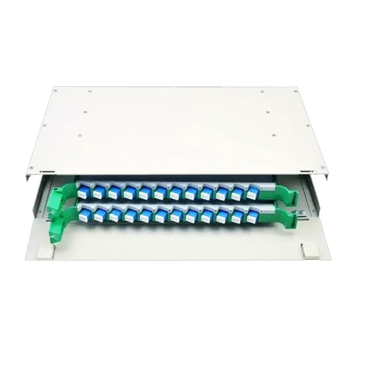
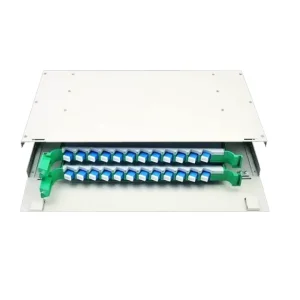
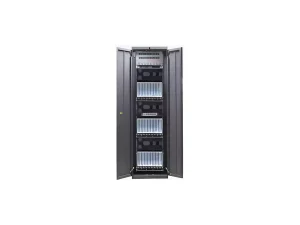
Large exchange or aggregation locations may need high-density frames, clear front-and-rear cable paths and documented port management. A 24-core ODF distribution unit can support smaller termination groups, while intelligent management requirements can be reviewed against the IODN product family. Outdoor distribution points require a separate review of sealing, cable entry, mounting, mechanical protection and the number of repeated technician interventions expected during the network life.
Pre-terminated assemblies can shorten work at locations where fusion splicing is restricted or where repeatable connector interfaces are preferred. Field-spliced construction remains useful when route lengths are uncertain or when cables must pass through small ducts. The project can combine both methods rather than treating them as competing network types.
Engineering and manufacturing support
Huijue Group can review OEM and private-label requirements for cable markings, packaging, enclosure appearance, port labels and documented assembly configurations. Drawing-based modifications are evaluated against optical routing, tooling, material, sealing, test and production requirements. Any final fiber grade, cable construction, connector performance or enclosure rating must be recorded in the approved specification rather than inferred from a category name.
For repeat deployments, a controlled site kit can group the cable, closure, splitter, adapters, patch cords, pigtails, labels and mounting accessories for a defined node type. This reduces ambiguity between the network drawing, warehouse issue list and field installation. Inspection points can also be agreed for cable length, continuity, polarity, connector end face and assembly labeling where applicable. A documented kit revision also helps purchasing and installation teams distinguish a deliberate design update from an accidental component substitution.
Information required for a project review
- Network topology and number of premises or service ports
- Feeder, distribution and drop-route lengths
- Required fiber type, fiber count and reserve policy
- Splitter architecture and optical loss budget
- Connector and polishing format
- Indoor, outdoor, aerial, duct or buried installation conditions
- Cabinet, closure and terminal-box mounting locations
- Local cable, fire, labeling and test requirements
- Quantity per node type and expected expansion stages
With those inputs, the project team can prepare a traceable product schedule rather than a generic FTTx package. Send the route and capacity brief for configuration review.
Product pathways
Related products
Use these products as configuration references. Final model selection depends on the approved project inputs.
Manufacturer support
Review the complete system before fixing the bill of materials
Huijue Group supports OEM, private-label and drawing-based customization subject to engineering review and the confirmed production scope.