
Passive optical distribution
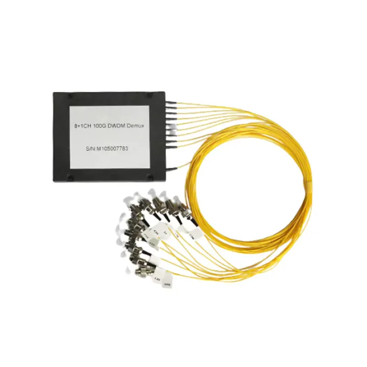
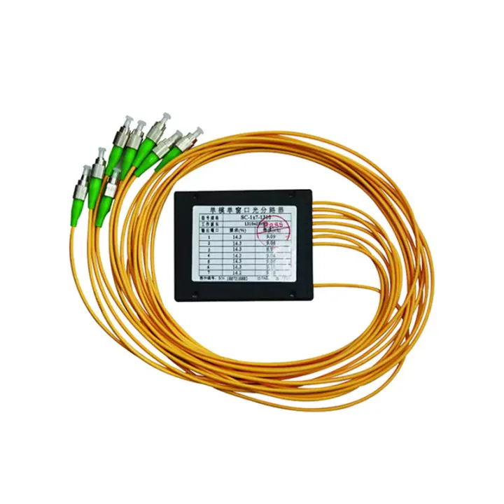
Match splitter or WDM architecture to wavelength plan, ratio, package and insertion-loss targets.
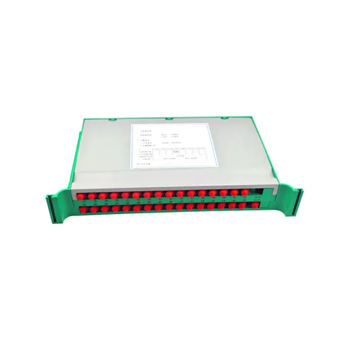
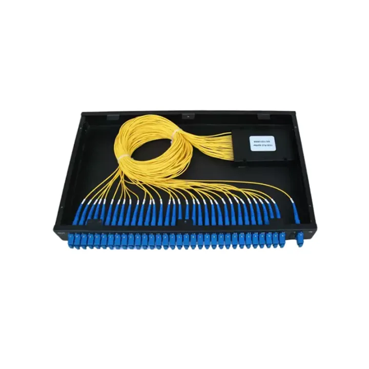
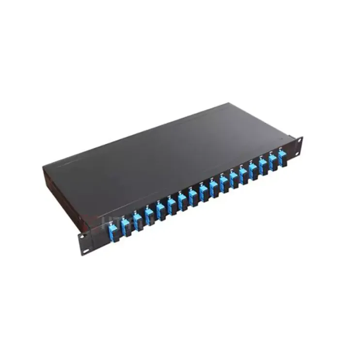
A 19-inch rack-mounted PLC splitter platform for organized 1×N or 2×N optical distribution in equipment rooms and central offices.
Subrack-Type Optical Splitter Series packages PLC splitting devices, adapters and connector management in a rack-mount chassis. The listed assembly fits a 19-inch rack and uses a 1U format for most configurations, placing passive optical distribution in a serviceable equipment-room location.
Available 1×N and 2×N ratios run from 4 to 64 outputs in the current optical tables. Higher split counts change chassis depth or height in the reference dimensions, so rack space, fiber routing and front-panel density must be checked for the selected ratio.
Specify input count, split ratio, connector and polish, input/output lead lengths, rack position and front/rear cable-routing method. Confirm the loss budget using the selected ratio and include adapter and patch-cord losses in the complete PON design.
Huijue Group can review OEM front-panel layouts, private-label markings, connector mixes and drawing-based rack assemblies. Port numbering, chassis dimensions, fiber map, optical grade, inspection plan and quantity must be approved; higher-density arrangements may require a different enclosure.
| Parameters | 1×4 | 1×8 | 1×16 | 1×32 | 1×64 | ||
| 1 | Operating Bandwidth (nm) | 1260 - 1650 | |||||
| 2 | Insertion Loss (dB) | Maximum | 7.4 | 10.5 | 13.8 | 17.1 | 20.4 |
| 3 | Polarization Dependent Loss (PDL) (dB) | Maximum | 0.2 | 0.2 | 0.3 | 0.3 | 0.3 |
| 4 | Return Loss (RL) (dB) | Minimum | 45 (PC); 50 (UPC); 55 (APC) | ||||
| 5 | Splitting Uniformity (dB) | Maximum | 0.7 | 0.8 | 1.0 | 1.5 | 2.0 |
| 6 | Directivity (dB) | Minimum | 55 | 55 | 55 | 55 | 55 |
Notes: 1. Applicable to uniform devices;
2. All parameters are tested including connectors, under the condition of λ=1310/1550nm.
3. The test wavelengths for splitting uniformity are 1310nm, 1490nm, and 1550nm. For the wavelength ranges of 1260nm-1300nm and 1600nm-1650nm, the splitting uniformity index is increased by 0.5dB on the basis of the above indicators.
| Parameters | 2×4 | 2×8 | 2×16 | 2×32 | 2×64 | ||
| 1 | Operating Bandwidth (nm) | 1260 - 1650 | |||||
| 2 | Insertion Loss (dB) | Maximum | 7.7 | 10.8 | 14.1 | 17.4 | 20.6 |
| 3 | Polarization Dependent Loss (PDL) (dB) | Maximum | 0.2 | 0.2 | 0.3 | 0.3 | 0.3 |
| 4 | Return Loss (RL) (dB) | Minimum | 45 (PC); 50 (UPC); 55 (APC) | ||||
| 5 | Splitting Uniformity (dB) | Maximum | 0.7 | 0.8 | 1.0 | 1.5 | 2.0 |
| 6 | Directivity (dB) | Minimum | 55 | 55 | 55 | 55 | 55 |
Notes: 1. Applicable to uniform devices;
2. All parameters are tested including connectors, under the condition of λ=1310/1550nm.
3. The test wavelengths for splitting uniformity are 1310nm, 1490nm, and 1550nm. For the wavelength ranges of 1260nm-1300nm and 1600nm-1650nm, the splitting uniformity index is increased by 0.5dB on the basis of the above indicators.
Install in a protected rack environment with adequate fiber-management space. Maintain bend radius, cap unused ports and ensure the rack and patching arrangement do not load the connector faces.
Buyer Questions
Answers specific to Subrack-Type Optical Splitter Series selection, configuration and purchasing.
No. The reference data shows larger dimensions for the highest ratios, so the exact enclosure must be checked.
A mixed panel can be reviewed from an approved drawing, subject to density, fiber routing and test requirements.
The PLC splitting function is passive; the rack arrangement is used for housing and fiber management.
Use the deployment context to narrow the configuration before comparing dimensions, capacities and options.
Match splitter or WDM architecture to wavelength plan, ratio, package and insertion-loss targets.
Coordinate connector, polish, fiber grade, polarity and cable length across patching points.
Plan MPO/MTP trunks and harnesses around port mapping, breakout format and rack density.
Select splicing, cleaning and test tools for the connector types and measurements used on site.
Before quotation: confirm capacity, interfaces, installation environment, power conditions, quantity and required options.