
Direct answer
An ODN should be planned as a complete passive path, not as a list of boxes. Start with the service architecture and optical budget, then place splitters, distribution nodes, closures, termination fields and reserved capacity where they can be installed, tested and maintained. Record every fibre, splice, connector and passive element that contributes loss, and preserve margin for construction variance and later work.
This pillar guide connects splitting, distribution, splicing, termination, capacity planning and optical-loss control. Use it to define project inputs before narrowing to a product family.

System boundaries to define before product selection
Plan passive optical distribution from the central office to subscriber termination. Start with the operating requirement and installation boundary, then separate system requirements from product claims so each supplier knows which evidence must accompany the offered configuration.
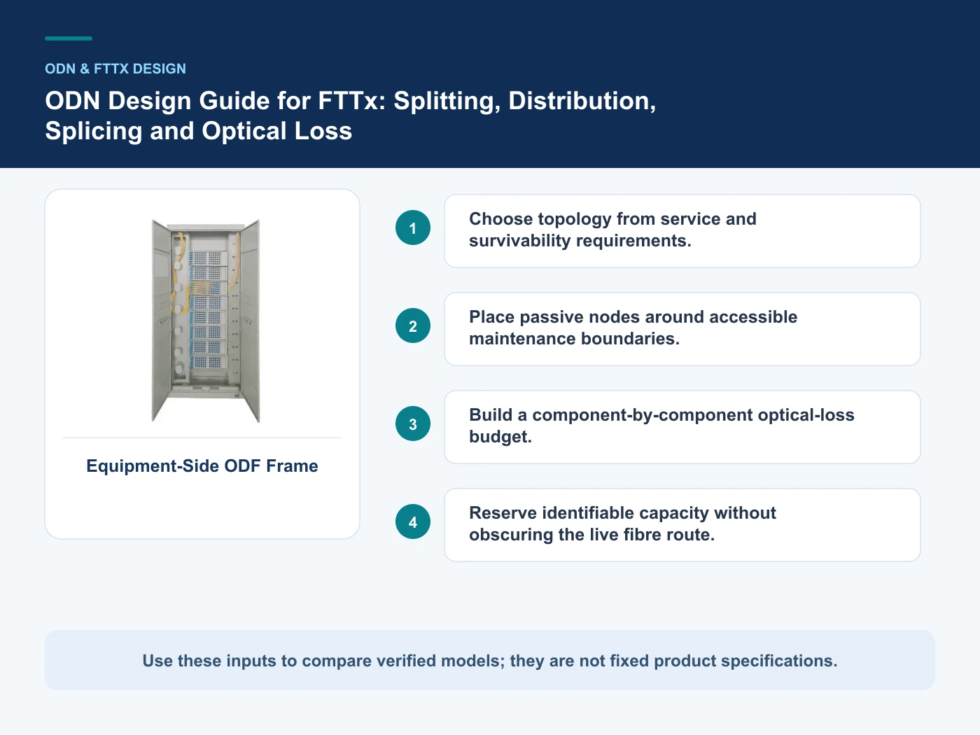
- Choose topology from service and survivability requirements.
- Place passive nodes around accessible maintenance boundaries.
- Build a component-by-component optical-loss budget.
- Reserve identifiable capacity without obscuring the live fibre route.
Choose topology from service and survivability requirements
Capture Topology and served premises, then use Central office as a practical comparison point: ODF and equipment-side termination. Before approval, verify this point: Organizes incoming cable, patch fields and equipment interfaces.
Place passive nodes around accessible maintenance boundaries
Capture Feeder and distribution fibre counts, then use Feeder/distribution boundary as a practical comparison point: Cross-connect or distribution cabinet. Before approval, verify this point: Supports rearrangement, splitting and route handoff.
Build a component-by-component optical-loss budget
Capture Splitter stages and package, then use Branch or splice point as a practical comparison point: Sealed closure. Before approval, verify this point: Protects splices and controlled branch entries.
Reserve identifiable capacity without obscuring the live fibre route
Capture Node capacity and mounting, then use Subscriber zone as a practical comparison point: Distribution/termination box. Before approval, verify this point: Combines drop access, adapters and optional splitters.
Architecture choices and verification boundaries
This table connects splitting, distribution, splicing, termination, capacity planning and optical-loss control to the decision on ODN network design. It is a decision aid rather than a universal performance table: exact capacity, environmental class, electrical or optical limits and certifications must come from the selected model, applicable project documents and verifiable test evidence.
| Option or input | When it fits | What must be verified |
|---|---|---|
| Central office | ODF and equipment-side termination | Organizes incoming cable, patch fields and equipment interfaces |
| Feeder/distribution boundary | Cross-connect or distribution cabinet | Supports rearrangement, splitting and route handoff |
| Branch or splice point | Sealed closure | Protects splices and controlled branch entries |
| Subscriber zone | Distribution/termination box | Combines drop access, adapters and optional splitters |
Reference point: ITU-T L.250: Topologies for optical access networks and ITU-T L.208: Requirements for passive optical nodes — distribution box frame the terminology or method used for this ODN network design comparison. They do not approve a product configuration; apply the edition named by the contract and local authority.
Set functional boundaries before choosing hardware
Divide the ODN into explicit functional boundaries: central-office termination, feeder route, distribution handoff, branching or splitting point, drop section and subscriber termination. For each boundary, state whether its purpose is termination, cross-connection, splitting, splicing, environmental protection or subscriber access. This prevents a cabinet, closure or box from being selected only because its nominal fibre capacity appears adequate. The relevant PON recommendation, such as ITU-T G.984 for a GPON context, establishes system assumptions but does not select the physical node arrangement for a particular route. ITU-T L-series guidance can support infrastructure planning, yet access, mounting, cable-entry geometry, maintenance practice and local installation conditions remain project decisions.
Make the loss budget auditable after construction
The design loss budget should show every planned contributor rather than one unexplained total. List fibre length, connectors, splices, splitter stages and any other passive elements using values whose source is identified, then separate engineering margin from calculated component loss. During handover, connect the budget to an as-built route, fibre identifiers, port map, splitter record and measurement files. A drawing without identifiers cannot reliably explain a failed path, while a test result without the intended route cannot confirm that the correct fibre was measured. Store closure entries, splice assignments, reserved fibres and patch-field positions in a form that technicians can update. When field conditions force a change, revise both the physical record and the budget instead of retaining an obsolete design total.
Procure a maintainable path rather than isolated capacities
Request quotations against a node schedule that states function, served premises, incoming and outgoing cable counts, splice quantity, adapter interface, splitter arrangement, mounting method, environmental location, cable-entry direction and required reserve. Ask bidders to mark which trays, adapters, pigtails, splitters, glands, mounting parts and labels are included, factory-installed or expected from another contractor. Capacity should be reviewed together with working space, bend control, splice storage, port access and the sequence of future expansion; a larger headline count is not useful if additions disturb live fibres. Compare proposals by the complete passive path and maintenance workflow. Freeze interface drawings and naming rules before manufacture, and define how substitutions or topology changes will be reviewed so procurement decisions remain aligned with the approved optical budget.
From requirements to an auditable project decision
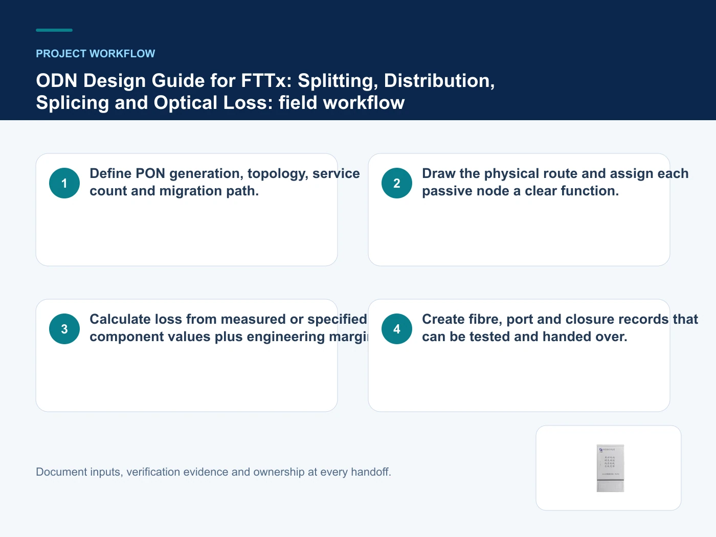
- Step 1: Define PON generation, topology, service count and migration path. Record Topology and served premises as an explicit input. Organizes incoming cable, patch fields and equipment interfaces.
- Step 2: Draw the physical route and assign each passive node a clear function. Record Feeder and distribution fibre counts as an explicit input. Supports rearrangement, splitting and route handoff.
- Step 3: Calculate loss from measured or specified component values plus engineering margin. Record Splitter stages and package as an explicit input. Protects splices and controlled branch entries.
- Step 4: Create fibre, port and closure records that can be tested and handed over. Record Node capacity and mounting as an explicit input. Combines drop access, adapters and optional splitters.
Relevant products from our communications portfolio
The products below connect the ODN network design decision to real catalogue families and verified site photography. They are starting points, not a claim that every configuration described here is a standard stock item; confirm model, interface, rating, drawing and testing scope with the project team.
- Equipment-Side ODF Frame — use this product page as a configuration reference when you choose topology from service and survivability requirements. Confirm the offered model, interfaces, drawings and available evidence before quotation.
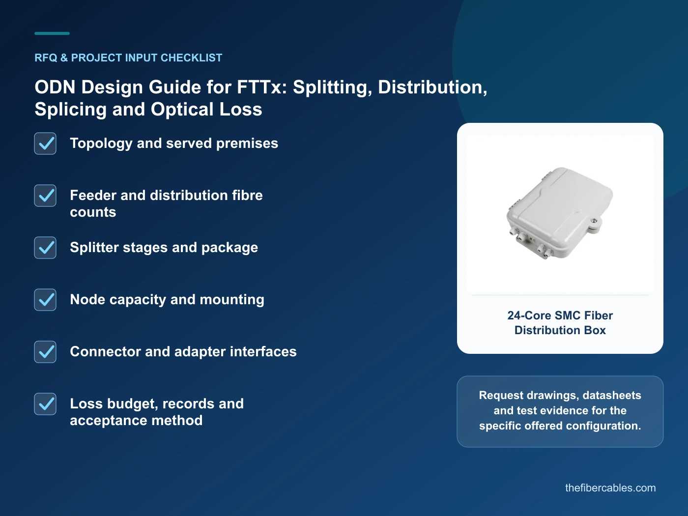
- 24-Core SMC Fiber Distribution Box — use this product page as a configuration reference when you place passive nodes around accessible maintenance boundaries. Confirm the offered model, interfaces, drawings and available evidence before quotation.
- Cassette-Type Jumper-Free Fiber Optic Cross-Connect Cabinet — use this product page as a configuration reference when you build a component-by-component optical-loss budget. Confirm the offered model, interfaces, drawings and available evidence before quotation.
For adjacent configurations, browse ODN & Fiber Distribution and compare those options against the ODN network design inputs above, including topology and served premises.
Common mistakes to avoid
- Using a theoretical splitter value as the entire loss budget.
- Choosing enclosure capacity without considering cable entries and splice storage.
- Assuming a nominal line rate is guaranteed user throughput.
What to include in the RFQ or design input
For ODN network design, a complete request reduces back-and-forth and prevents a catalogue image from being mistaken for a verified configuration. Record the following fields, identify which values are mandatory or provisional and attach route, interface or layout drawings where relevant.
- Topology and served premises
- Feeder and distribution fibre counts
- Splitter stages and package
- Node capacity and mounting
- Connector and adapter interfaces
- Loss budget, records and acceptance method
Questions engineers and buyers ask
What should be fixed before selecting products for ODN network design?
Define topology and served premises, feeder and distribution fibre counts, splitter stages and package first, then compare product evidence against the complete system boundary rather than one catalogue value.
How should a ODN network design decision be documented?
Keep the route or architecture drawing, decision assumptions, selected configuration, verification evidence and acceptance records under the same revision process.
Sources and standards
For ODN network design, the references below define relevant terminology, scope or test methods. ITU-T L.250: Topologies for optical access networks is one documented boundary for this topic; neither a standards catalogue page nor a category page proves certification of the offered product. Apply the edition adopted by the contract, destination market and authority having jurisdiction.
- ITU-T L.250: Topologies for optical access networks (01/2024). Use it to verify the terminology and scope relevant to ODN network design; the source does not certify a specific offered product.
- ITU-T L.208: Requirements for passive optical nodes — distribution box (08/2019). Use it to verify the terminology and scope relevant to ODN network design; the source does not certify a specific offered product.
- ITU-T L.201: Outdoor sealed closures for optical fibre cables (05/2021). Use it to verify the terminology and scope relevant to ODN network design; the source does not certify a specific offered product.
- ITU-T G.984.1: Gigabit-capable passive optical networks — General characteristics (03/2008 with amendments). Use it to verify the terminology and scope relevant to ODN network design; the source does not certify a specific offered product.
Source review: Links and cited editions for ODN network design were checked on 2026-10-15. Confirm the edition adopted by the project contract and the authority having jurisdiction.
Related guidance
ODF vs Fiber Distribution Box vs Optical Cross-Connect Cabinet: Where Each Fits • How to Build an Optical Loss Budget for GPON and XGS-PON • Choosing 8-, 16-, 24- or 48-Core Fiber Distribution Boxes
Prepare a ODN network design configuration for review
Send topology and served premises, feeder and distribution fibre counts, splitter stages and package, node capacity and mounting, together with quantity and delivery destination. We will help narrow the relevant product family and identify the drawings or test evidence needed for quotation.
——END——