
Direct answer
ODF capacity planning starts by separating outside-plant cable termination, equipment-side patching, cross-connection, splicing, pass-through fibres and reserve. The frame must also accept the actual cable-entry direction, bend-controlled routing, jumper management, grounding where applicable, labelling and technician access. A high nominal core count is not useful if patch fields, trays, vertical managers or cable entries become inaccessible during expansion.
Within the broader ODN & FTTx Design workflow, this article focuses on ODF capacity planning: plan ODF capacity and growth as a maintainable system. Confirm line/equipment fibre counts and the evidence for the offered product before final engineering approval.
Inputs required before any calculation
Plan ODF capacity and growth as a maintainable system. Start with the operating requirement and installation boundary, then separate system requirements from product claims so each supplier knows which evidence must accompany the offered configuration.
- Separate line-side and equipment-side functions.
- Forecast ports and fibres by service phase.
- Lay out jumper paths and cable entries.
- Reserve modules in named, documented blocks.
Separate line-side and equipment-side functions
Capture Line/equipment fibre counts, then use Line side as a practical comparison point: OSP cable termination and splice organization. Before approval, verify this point: Plan cable entries, trays and grounding.
Forecast ports and fibres by service phase
Capture Connector interfaces, then use Equipment side as a practical comparison point: Patch interfaces toward active equipment. Before approval, verify this point: Match connectors and maintenance workflow.
Lay out jumper paths and cable entries
Capture Splice trays, then use Cross-connect field as a practical comparison point: Rearrangeable jumper paths. Before approval, verify this point: Management capacity must grow with ports.
Reserve modules in named, documented blocks
Capture Cable entries, then use Line side as a practical comparison point: OSP cable termination and splice organization. Before approval, verify this point: Plan cable entries, trays and grounding.
A traceable sizing and verification workflow
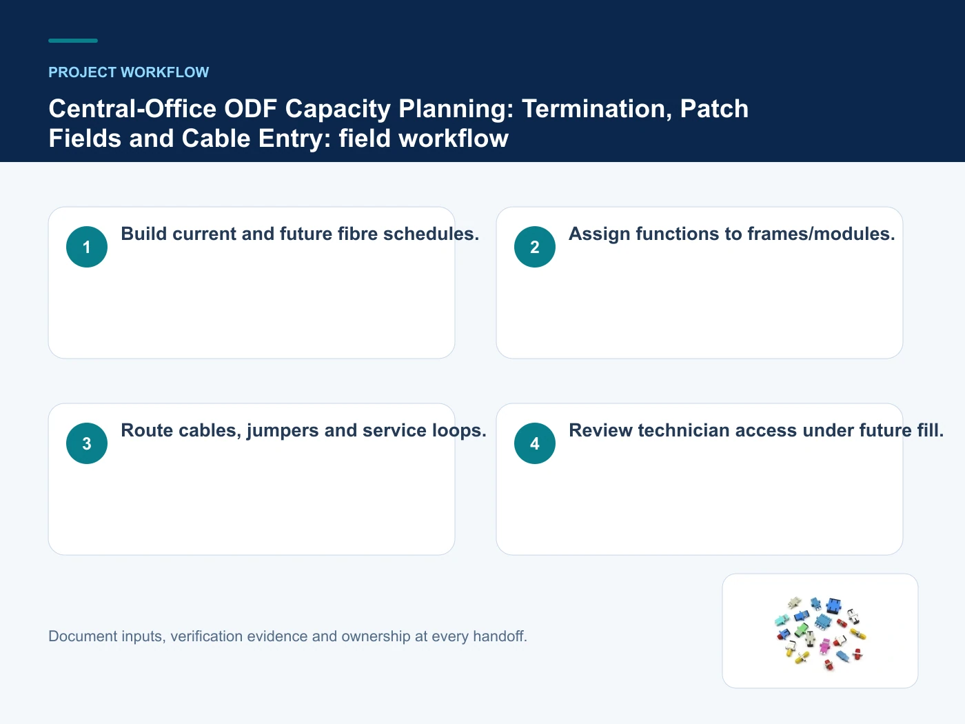
- Step 1: Build current and future fibre schedules. Record Line/equipment fibre counts as an explicit input. Plan cable entries, trays and grounding.
- Step 2: Assign functions to frames/modules. Record Connector interfaces as an explicit input. Match connectors and maintenance workflow.
- Step 3: Route cables, jumpers and service loops. Record Splice trays as an explicit input. Management capacity must grow with ports.
- Step 4: Review technician access under future fill. Record Cable entries as an explicit input. Plan cable entries, trays and grounding.
Calculation boundaries and acceptance limits
This table connects splitting, distribution, splicing, termination, capacity planning and optical-loss control to the decision on ODF capacity planning. It is a decision aid rather than a universal performance table: exact capacity, environmental class, electrical or optical limits and certifications must come from the selected model, applicable project documents and verifiable test evidence.
| Option or input | When it fits | What must be verified |
|---|---|---|
| Line side | OSP cable termination and splice organization | Plan cable entries, trays and grounding |
| Equipment side | Patch interfaces toward active equipment | Match connectors and maintenance workflow |
| Cross-connect field | Rearrangeable jumper paths | Management capacity must grow with ports |
Reference point: ITU-T L.202: Optical distribution frames and ITU-T L.250: Topologies for optical access networks frame the terminology or method used for this ODF capacity planning comparison. They do not approve a product configuration; apply the edition named by the contract and local authority.
Relevant products from our communications portfolio
The products below connect the ODF capacity planning decision to real catalogue families and verified site photography. They are starting points, not a claim that every configuration described here is a standard stock item; confirm model, interface, rating, drawing and testing scope with the project team.
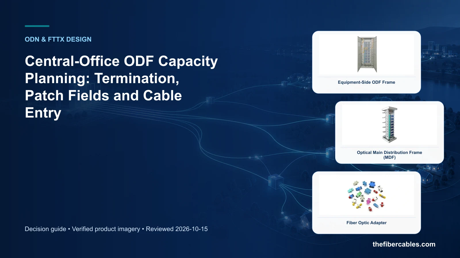
- Equipment-Side ODF Frame — use this product page as a configuration reference when you separate line-side and equipment-side functions. Confirm the offered model, interfaces, drawings and available evidence before quotation.
- Optical Main Distribution Frame (MDF) — use this product page as a configuration reference when you forecast ports and fibres by service phase. Confirm the offered model, interfaces, drawings and available evidence before quotation.
- Fiber Optic Adapter — use this product page as a configuration reference when you lay out jumper paths and cable entries. Confirm the offered model, interfaces, drawings and available evidence before quotation.
For adjacent configurations, browse ODN & Fiber Distribution and compare those options against the ODF capacity planning inputs above, including line/equipment fibre counts.
What to include in the RFQ or design input
For ODF capacity planning, a complete request reduces back-and-forth and prevents a catalogue image from being mistaken for a verified configuration. Record the following fields, identify which values are mandatory or provisional and attach route, interface or layout drawings where relevant.
- Line/equipment fibre counts
- Connector interfaces
- Splice trays
- Cable entries
- Jumper managers
- Growth and labelling
Common mistakes to avoid
- Counting adapters without jumper-management space.
- Mixing line/equipment records.
- Reserving unlabeled capacity that cannot be traced.
Questions engineers and buyers ask
Can ODF capacity planning be sized from a nominal rating alone?
No. The calculation must include line/equipment fibre counts, connector interfaces, splice trays plus applicable margins, derating and acceptance limits.
Which result should appear in the RFQ?
State the design inputs, calculation method, selected value, reserve or margin and evidence required from the offered configuration.
Sources and standards
For ODF capacity planning, the references below define relevant terminology, scope or test methods. ITU-T L.202: Optical distribution frames is one documented boundary for this topic; neither a standards catalogue page nor a category page proves certification of the offered product. Apply the edition adopted by the contract, destination market and authority having jurisdiction.
- ITU-T L.202: Optical distribution frames (07/2010). Use it to verify the terminology and scope relevant to ODF capacity planning; the source does not certify a specific offered product.
- ITU-T L.250: Topologies for optical access networks (01/2024). Use it to verify the terminology and scope relevant to ODF capacity planning; the source does not certify a specific offered product.
Source review: Links and cited editions for ODF capacity planning were checked on 2026-10-15. Confirm the edition adopted by the project contract and the authority having jurisdiction.
Related guidance
ODN Design Guide for FTTx: Splitting, Distribution, Splicing and Optical Loss • Dome vs Horizontal Fiber Closure: Capacity, Ports and Installation Trade-Offs • ODF vs Fiber Distribution Box vs Optical Cross-Connect Cabinet: Where Each Fits
Prepare a ODF capacity planning configuration for review
Send line/equipment fibre counts, connector interfaces, splice trays, cable entries, together with quantity and delivery destination. We will help narrow the relevant product family and identify the drawings or test evidence needed for quotation.
——END——