
Passive optical distribution
Match splitter or WDM architecture to wavelength plan, ratio, package and insertion-loss targets.
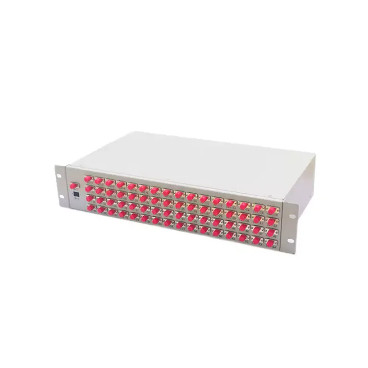
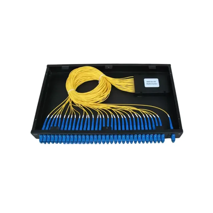
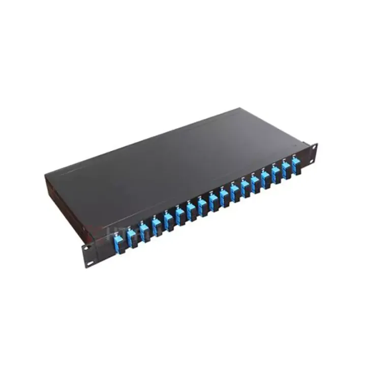
A tray-format PLC splitter for installation inside fiber distribution frames and optical cross-connect cabinets, with 1×N and 2×N ratios.
Tray-Type Optical Splitter Series places a PLC splitter and connector interfaces in a format intended for fiber distribution frames or optical cross-connect cabinets. Compared with a standalone box, the tray integrates with existing management hardware and keeps split outputs accessible for maintenance.
The current data covers 1×4 to 1×64 and 2×4 to 2×64 ratios over 1260–1650 nm. Reference tray height increases at 32- and 64-way ratios, so the usable bay, guide rails and fiber slack space must be verified before selection.
Confirm the host frame or cabinet, tray mounting dimensions, split ratio, input count, connector/polish, lead diameter and cable-entry direction. Use the selected ratio's insertion-loss and uniformity data in the optical budget.
Huijue Group can review sample-matched or drawing-based trays, port labels and private-label markings. Connector mix, mounting points, fiber routing, materials, optical test scope and volume remain subject to engineering approval.
| Parameters | 1×4 | 1×8 | 1×16 | 1×32 | 1×64 | ||
| 1 | Operating Bandwidth (nm) | 1260 - 1650 | |||||
| 2 | Insertion Loss (dB) | Maximum | 7.4 | 10.5 | 13.8 | 17.1 | 20.4 |
| 3 | Polarization Dependent Loss (PDL) (dB) | Maximum | 0.2 | 0.2 | 0.3 | 0.3 | 0.3 |
| 4 | Return Loss (RL) (dB) | Minimum | 45 (PC); 50 (UPC); 55 (APC) | ||||
| 5 | Splitting Uniformity (dB) | Maximum | 0.7 | 0.8 | 1.0 | 1.5 | 2.0 |
| 6 | Directivity (dB) | Minimum | 55 | 55 | 55 | 55 | 55 |
Notes: 1. Applicable to devices with all included components;
2. All parameters are tested including connectors, under the condition of λ=1310/1550nm.
3. The test wavelengths for splitting uniformity are 1310nm, 1490nm, and 1550nm. For the wavelength ranges of 1260nm-1300nm and 1600nm-1650nm, the splitting uniformity index is increased by 0.5dB on the basis of the above indicators.
| Parameters | 2×4 | 2×8 | 2×16 | 2×32 | 2×64 | ||
| 1 | Operating Bandwidth (nm) | 1260 - 1650 | |||||
| 2 | Insertion Loss (dB) | Maximum | 7.7 | 10.8 | 14.1 | 17.4 | 20.6 |
| 3 | Polarization Dependent Loss (PDL) (dB) | Maximum | 0.2 | 0.2 | 0.3 | 0.3 | 0.3 |
| 4 | Return Loss (RL) (dB) | Minimum | 45 (PC); 50 (UPC); 55 (APC) | ||||
| 5 | Splitting Uniformity (dB) | Maximum | 0.7 | 0.8 | 1.0 | 1.5 | 2.0 |
| 6 | Directivity (dB) | Minimum | 55 | 55 | 55 | 55 | 55 |
Notes: 1. Applicable to uniform devices;
2. All parameters are tested including connectors, under the condition of λ=1310/1550nm.
3. The test wavelengths for splitting uniformity are 1310nm, 1490nm, and 1550nm. For the wavelength ranges of 1260nm-1300nm and 1600nm-1650nm, the splitting uniformity index is increased by 0.5dB on the basis of the above indicators.
The host frame or cabinet provides environmental and mechanical protection. Keep fiber slack controlled, preserve bend radius and prevent tray movement from loading the splitter leads.
Buyer Questions
Answers specific to Tray-Type Optical Splitter Series selection, configuration and purchasing.
Only when mounting dimensions, guides, cable routing and port clearance match. Provide the host-cabinet drawing or sample.
More splitter and connector capacity needs additional internal space; the reference data increases height for 1×32/2×32 and 1×64/2×64 formats.
Use the deployment context to narrow the configuration before comparing dimensions, capacities and options.
Match splitter or WDM architecture to wavelength plan, ratio, package and insertion-loss targets.
Coordinate connector, polish, fiber grade, polarity and cable length across patching points.
Plan MPO/MTP trunks and harnesses around port mapping, breakout format and rack density.
Select splicing, cleaning and test tools for the connector types and measurements used on site.
Before quotation: confirm capacity, interfaces, installation environment, power conditions, quantity and required options.