
Direct answer
A brownfield telecom power retrofit should begin with measured load, the existing DC voltage window, battery condition, distribution limits, alarm interfaces and the permitted service interruption. The safe planning sequence is to document the installed system, define the future load and autonomy case, identify compatibility boundaries, and design a controlled cutover with rollback provisions. A new rectifier shelf or lithium battery cannot be approved only because its nominal voltage matches the site: protection settings, cable capacity, grounding, controller logic, communications and physical fit also need review. Keep the existing and proposed single-line diagrams under revision control, separate temporary works from the final configuration, and require model-specific drawings and test records before site work. The cited standards define interfaces or safety frameworks; they do not certify the offered retrofit package.
This pillar guide connects -48 V plant retrofit, rectifiers, recharge, disconnect logic, protection, distribution and equipment interfaces. Use it to define project inputs before narrowing to a product family.
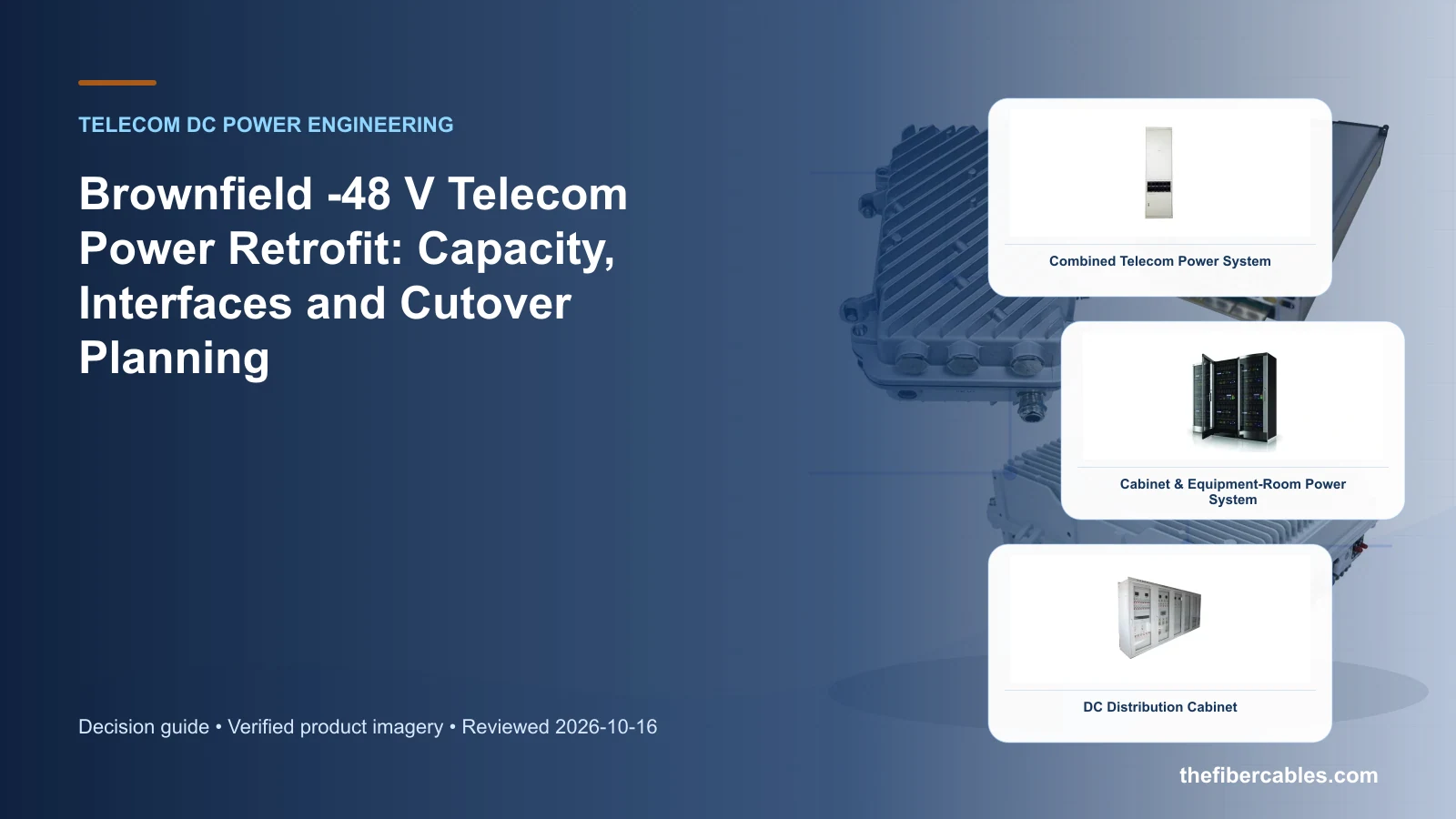
Existing-site facts to verify before the upgrade
Plan an existing-site power upgrade without treating new rectifiers, distribution and batteries as isolated replacements. Start with the operating requirement and installation boundary, then separate system requirements from product claims so each supplier knows which evidence must accompany the offered configuration.
- Establish the present peak load, battery recharge demand and documented growth case.
- Map voltage, grounding, protection, alarm and communications interfaces before selecting replacement hardware.
- Choose whether the upgrade is staged beside the live plant or completed during an approved outage.
- Define acceptance, rollback and as-built records before the cutover method is released.
Establish the present peak load, battery recharge demand and documented growth case
Capture Existing single-line diagram, then use Parallel staged upgrade as a practical comparison point: Space and interfaces allow a new plant beside the live system. Before approval, verify this point: Temporary feeds, current sharing and final transfer sequence.
Map voltage, grounding, protection, alarm and communications interfaces before selecting replacement hardware
Capture Measured normal and peak load, then use In-place component replacement as a practical comparison point: Existing cabinet and distribution remain serviceable. Before approval, verify this point: Mechanical fit, controller compatibility and protection settings.
Choose whether the upgrade is staged beside the live plant or completed during an approved outage
Capture Battery and recharge requirement, then use Complete plant replacement as a practical comparison point: Capacity, condition or architecture makes partial reuse impractical. Before approval, verify this point: Outage window, temporary supply and rollback plan.
Define acceptance, rollback and as-built records before the cutover method is released
Capture DC voltage and grounding arrangement, then use Parallel staged upgrade as a practical comparison point: Space and interfaces allow a new plant beside the live system. Before approval, verify this point: Temporary feeds, current sharing and final transfer sequence.
Retrofit paths, constraints and cutover exposure
This table connects -48 V plant retrofit, rectifiers, recharge, disconnect logic, protection, distribution and equipment interfaces to the decision on telecom power system retrofit. It is a decision aid rather than a universal performance table: exact capacity, environmental class, electrical or optical limits and certifications must come from the selected model, applicable project documents and verifiable test evidence.
| Option or input | When it fits | What must be verified |
|---|---|---|
| Parallel staged upgrade | Space and interfaces allow a new plant beside the live system | Temporary feeds, current sharing and final transfer sequence |
| In-place component replacement | Existing cabinet and distribution remain serviceable | Mechanical fit, controller compatibility and protection settings |
| Complete plant replacement | Capacity, condition or architecture makes partial reuse impractical | Outage window, temporary supply and rollback plan |
Reference point: ETSI EN 300 132-2: Power supply interface at the input of ICT equipment — -48 V direct current and ITU-T L.1210: Sustainable power-feeding solutions for 5G network frame the terminology or method used for this telecom power system retrofit comparison. They do not approve a product configuration; apply the edition named by the contract and local authority.
Reconcile the live plant before designing the replacement
Survey labels, cable sizes, protective devices, controller settings, alarms, batteries and measured load, then reconcile them with the latest drawing. A retrofit plan based on an outdated single-line diagram can miss undocumented changes and temporary feeds.
Separate retained equipment from items to be replaced and identify every electrical, mechanical and communications interface between them.
Model normal, recovery and degraded operation
The future plant must support the live load, permitted battery recharge and defined growth while respecting input, cable, distribution and thermal limits. Review failed-module or maintenance states separately from the normal case.
Compatibility includes voltage windows, protection, grounding, alarms, controller behavior, connectors, airflow and physical access. A matching nominal voltage does not close those interfaces.
Treat cutover and rollback as engineering deliverables
Define temporary power, switching sequence, hold points, communication checks, acceptance measurements and the condition that triggers rollback. Assign each step to a responsible party before the outage window begins.
After cutover, update settings, labels, alarms, single-line diagrams and as-built records together so the operating team inherits one coherent configuration.
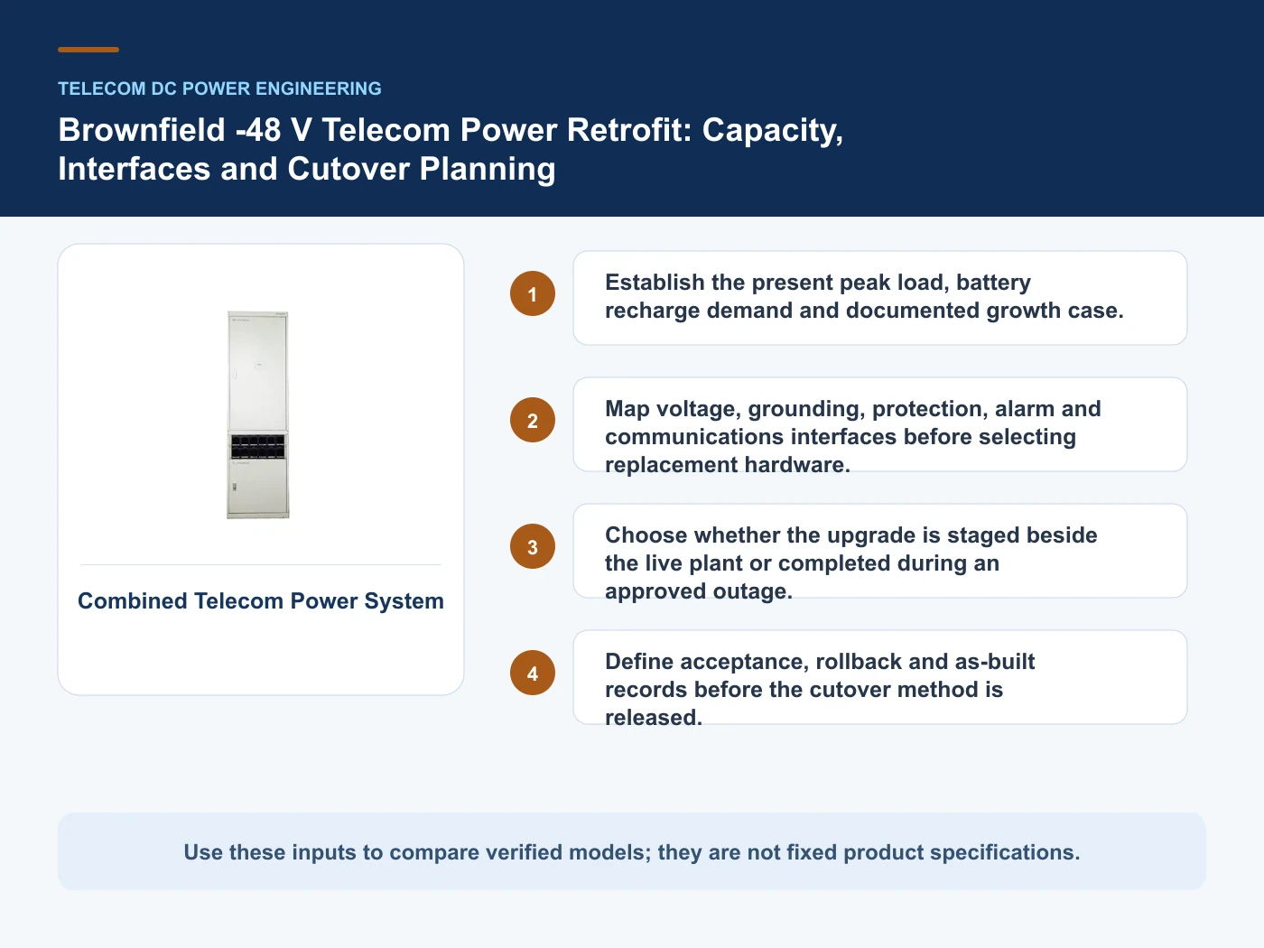
Survey, design, cutover and as-built handover
- Step 1: Survey the installed plant and reconcile drawings with labels, cable sizes, protection and live measurements. Record Existing single-line diagram as an explicit input. Temporary feeds, current sharing and final transfer sequence.
- Step 2: Build the future load, recharge, redundancy and autonomy cases without assuming unused nameplate capacity is available. Record Measured normal and peak load as an explicit input. Mechanical fit, controller compatibility and protection settings.
- Step 3: Review mechanical, electrical, monitoring and grounding compatibility for every retained and replaced interface. Record Battery and recharge requirement as an explicit input. Outage window, temporary supply and rollback plan.
- Step 4: Approve a method statement covering temporary power, cutover, verification, rollback and as-built handover. Record DC voltage and grounding arrangement as an explicit input. Temporary feeds, current sharing and final transfer sequence.
Relevant products from our communications portfolio
The products below connect the telecom power system retrofit decision to real catalogue families and verified site photography. They are starting points, not a claim that every configuration described here is a standard stock item; confirm model, interface, rating, drawing and testing scope with the project team.
- Cabinet-Type Telecom DC Power System (HDUM01-48) — use this product page as a configuration reference when you establish the present peak load, battery recharge demand and documented growth case. Confirm the offered model, interfaces, drawings and available evidence before quotation.
- Cabinet-Type Telecom DC Power System (HJ-DYZ-600) — use this product page as a configuration reference when you map voltage, grounding, protection, alarm and communications interfaces before selecting replacement hardware. Confirm the offered model, interfaces, drawings and available evidence before quotation.
- DC Distribution Cabinet — use this product page as a configuration reference when you choose whether the upgrade is staged beside the live plant or completed during an approved outage. Confirm the offered model, interfaces, drawings and available evidence before quotation.
- Wall-Mounted Power System — use this product page as a configuration reference when you define acceptance, rollback and as-built records before the cutover method is released. Confirm the offered model, interfaces, drawings and available evidence before quotation.
For adjacent configurations, browse Telecom Power & Site Energy and compare those options against the telecom power system retrofit inputs above, including existing single-line diagram.
Common mistakes to avoid
- Selecting a new shelf from nominal voltage and rated current alone.
- Using an old single-line diagram without confirming the installed distribution and cable routes.
- Leaving temporary power, rollback ownership and alarm remapping until the outage begins.
What to include in the RFQ or design input
For telecom power system retrofit, a complete request reduces back-and-forth and prevents a catalogue image from being mistaken for a verified configuration. Record the following fields, identify which values are mandatory or provisional and attach route, interface or layout drawings where relevant.
- Existing single-line diagram
- Measured normal and peak load
- Battery and recharge requirement
- DC voltage and grounding arrangement
- Distribution and cable schedule
- Alarm and protocol list
Questions engineers and buyers ask
How should parallel staged upgrade be evaluated for telecom power system retrofit?
Use space and interfaces allow a new plant beside the live system as the operating context, record existing single-line diagram, and verify temporary feeds, current sharing and final transfer sequence for the exact offered configuration.
Which project input can change the telecom power system retrofit decision?
Establish the present peak load, battery recharge demand and documented growth case. Recheck that decision when measured normal and peak load or battery and recharge requirement changes.
Sources and standards
These sources support the method and vocabulary used in this guide. They are not a substitute for project requirements or evidence tied to the exact telecom power system retrofit configuration.
- ETSI EN 300 132-2: Power supply interface at the input of ICT equipment — -48 V direct current (V2.8.1, 2024). Use it to verify the terminology and scope relevant to telecom power system retrofit; the source does not certify a specific offered product.
- ITU-T L.1210: Sustainable power-feeding solutions for 5G network (In force; reviewed 2026-10-16). Use it to verify the terminology and scope relevant to telecom power system retrofit; the source does not certify a specific offered product.
- IEC 61439-1: Low-voltage switchgear and controlgear assemblies — General rules (2020, Ed. 3). Use it to verify the terminology and scope relevant to telecom power system retrofit; the source does not certify a specific offered product.
- IEC 62477-1: Safety requirements for power electronic converter systems and equipment (2022, Ed. 2). Use it to verify the terminology and scope relevant to telecom power system retrofit; the source does not certify a specific offered product.
Source review: Links and cited editions for telecom power system retrofit were checked on 2026-10-16. Confirm the edition adopted by the project contract and the authority having jurisdiction.
Related guidance
Telecom Rectifier Module Replacement: Voltage Window, Shelf Fit, Protocol and Derating • Rectifier Capacity After an Outage: Why Battery Recharge Current Changes the Calculation • LVD vs BLVD in Telecom DC Power Systems: Load Priority and Battery Protection
Prepare a telecom power system retrofit configuration for review
For a project review, provide existing single-line diagram, measured normal and peak load, battery and recharge requirement, dc voltage and grounding arrangement. The response can separate standard options, customization points and information still required before quotation.
——END——