
Data Center Solutions
Data Center & Network Infrastructure
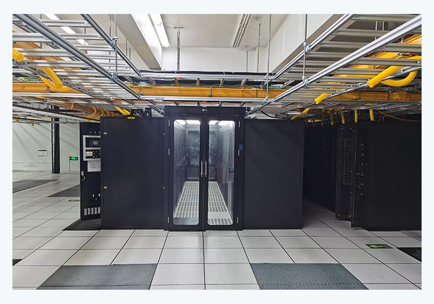
Coordinate racks, micro-modules, power distribution, airflow containment, cable pathways and fiber connectivity around equipment load, room constraints and future expansion.
Planning and configuration
Solution overview
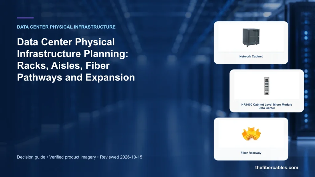
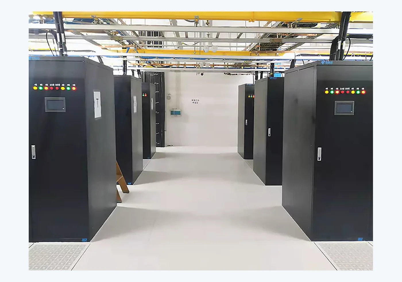
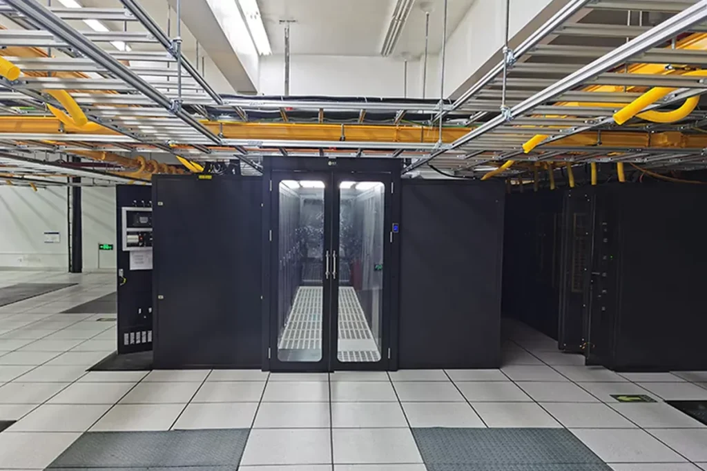
Data-center infrastructure must make IT equipment installable, powerable, coolable and maintainable within the same physical plan. Huijue Group’s scope can combine network and server cabinets, micro-module infrastructure, aisle containment, row-end distribution, rack PDUs, cable pathways, optical distribution and environmental monitoring. The solution is configured for the room and equipment schedule; it is not a claim that every project needs a complete prefabricated module.
A compact edge room may require only several coordinated racks and a clear power and cable layout. A new equipment hall may benefit from repeatable rows, contained airflow and modular expansion. Existing rooms often need phased work so that cable paths, power distribution or cabinets can be upgraded without treating the entire facility as a greenfield project.
Start with the equipment schedule and room boundary
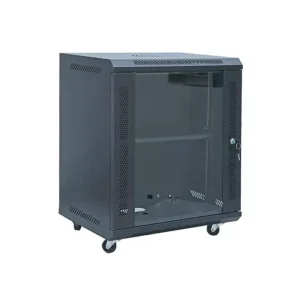
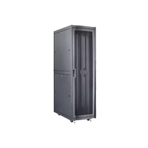
Rack selection begins with usable rack units, equipment depth, weight, front-to-rear airflow and connector access. These inputs determine cabinet depth, door style, rail position, static loading and the clearance required for installation and maintenance. Products such as the network cabinet and IDC server cabinet provide a mechanical base, but the final arrangement depends on what will be installed inside them.
The room survey should record ceiling height, column positions, floor loading, delivery route, raised-floor or slab conditions, available electrical feeds, cooling interfaces, fire-protection constraints and the permitted cable-entry directions. A scaled layout can then reserve service aisles, door swing, replacement paths and future rack positions before production dimensions are frozen.
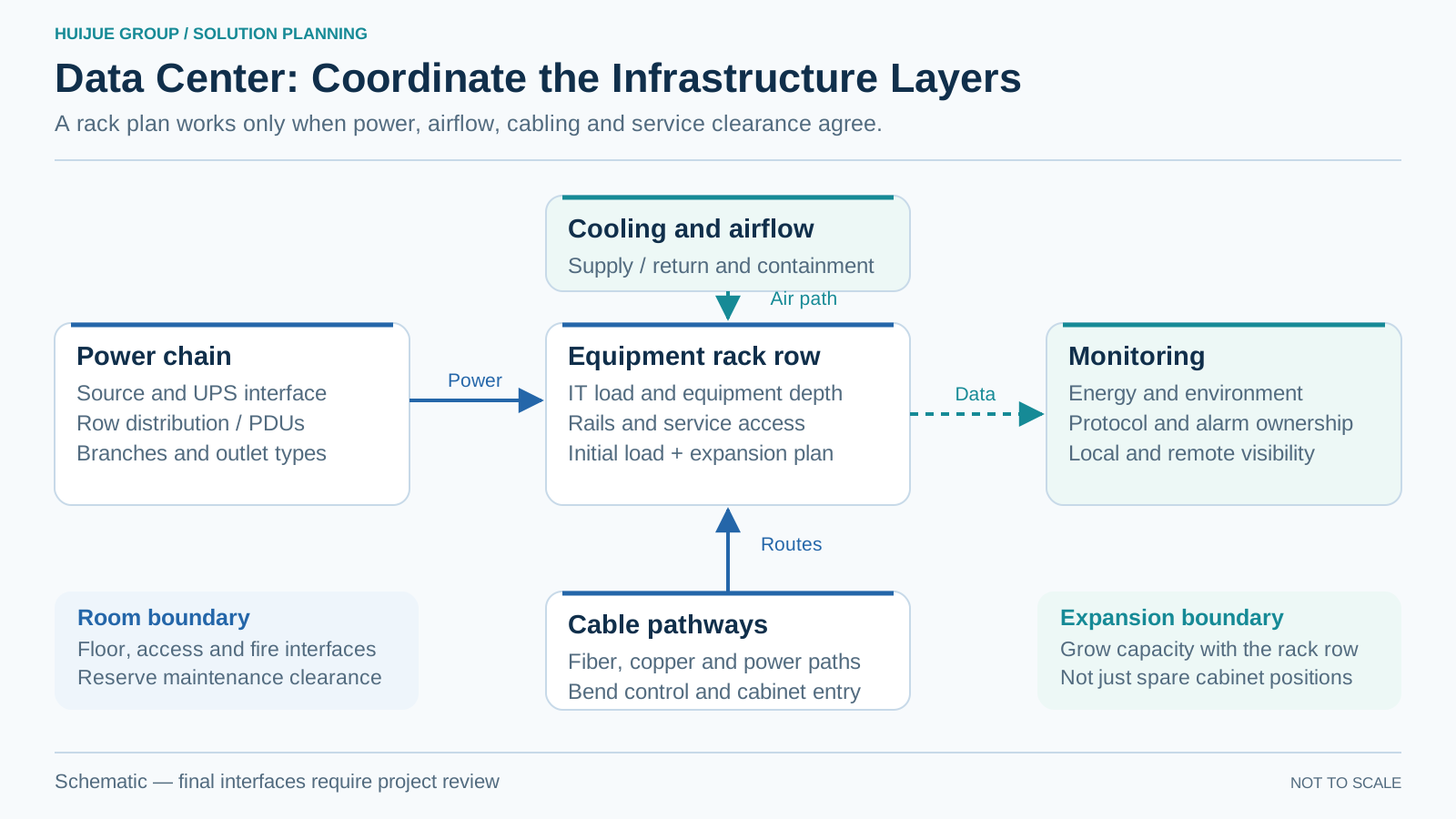
Coordinate five infrastructure layers
- Equipment housing: select rack height, width and depth from the IT and network equipment rather than headline capacity alone.
- Power chain: map upstream supply, UPS interface, row distribution, branch protection and rack PDU outlets to the real load schedule and redundancy objective.
- Airflow: align equipment orientation, blanking panels and containment. A Standard Cold Aisle Containment System should be considered only after cooling delivery and return paths are understood.
- Cabling: separate optical, copper and power paths where required; establish overhead or underfloor routes, bend control and cabinet entry before cable quantities are released.
- Monitoring: identify the environmental and power points that must be visible, the protocol used by the site platform and the alarm ownership.
When a micro-module is appropriate
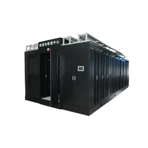
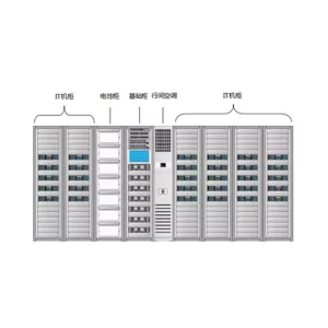
Micro-module products group several infrastructure functions into a repeatable deployment unit. The HR2000 row-level micro-module, for example, is relevant where a compact row needs coordinated cabinets and supporting systems. Selection still requires a project-specific review of IT load, redundancy, cooling method, available supply, fire strategy and room geometry. A module can reduce interfaces between packages, but it does not replace load calculation or site coordination.
For smaller facilities, an all-in-one infrastructure cabinet or a short row may provide a cleaner scope than a full enclosed aisle. For expansion projects, matching cabinet geometry, PDU outlet format, cable pathways and monitoring points with the installed estate may be more important than adopting a new product family.
- Equipment boundary
- The device schedule sets usable rack space, depth, loading, airflow and connector access. A cabinet count alone cannot settle those requirements.
- Room boundary
- The room drawing sets delivery access, floor conditions, service aisles, cable routes and connections to electrical, cooling and fire systems.
- Supply boundary
- The order should distinguish factory-supplied cabinets and assemblies from upstream works, room services and IT equipment supplied by others. This keeps the interfaces visible when the project is divided between contractors.
Power and cable details that prevent rework
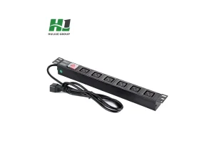
A rack PDU should be specified by input plug, rated current, outlet type and quantity, phase arrangement, mounting orientation and any metering or switching requirement. Upstream and downstream protective devices need engineering coordination. Likewise, fiber and copper cabling should be scheduled by origin, destination, route, connector format and slack method. Naming these details in the drawing prevents a nominally correct cabinet from arriving with unusable outlet or entry arrangements.
Manufacturing and project support
Huijue Group can review custom cabinet dimensions, doors, panels, cable openings, rail positions, color, labels and accessory sets, as well as coordinated row and pathway layouts. OEM or private-label work is subject to drawing approval, material feasibility, tooling, production quantity and the tests defined for the order. The manufacturing package should identify interfaces that remain by others, particularly upstream electrical works, room cooling, civil works, fire systems and IT equipment.
For a cabinet, short row or transportable computing node, use the focused modular data center planning guide to define the deployment unit and the factory-to-site interfaces before finalizing the broader room infrastructure.
Inputs for a focused configuration
- Room drawing, access route and installation phases
- Rack count, equipment list, dimensions, weight and airflow direction
- Continuous and design IT load per rack
- Power topology, voltage, phases and redundancy objective
- PDU input and outlet schedule
- Cooling delivery and return-air arrangement
- Optical, copper and power cable quantities and routes
- Monitoring points and communication protocol
- Required spare positions and expansion sequence
- Applicable local electrical, fire and construction requirements
Share the room drawing and equipment schedule so the physical, power and cabling scope can be reviewed together.
Product pathways
Related products
Use these products as configuration references. Final model selection depends on the approved project inputs.
Manufacturer support
Review the complete system before fixing the bill of materials
Huijue Group supports OEM, private-label and drawing-based customization subject to engineering review and the confirmed production scope.